STM-S3E 데이터 시트보기 (PDF) - Unspecified
부품명
상세내역
제조사
STM-S3E Datasheet PDF : 16 Pages
| |||
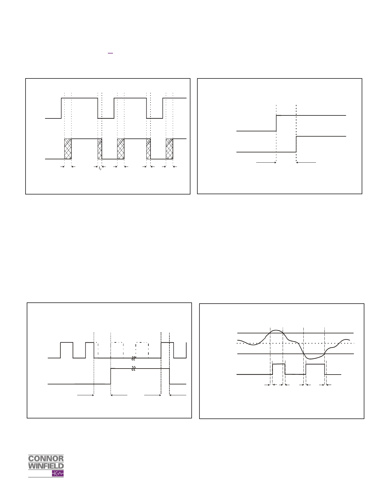
3E Phase Build Out > 34 ppm
Frequency Change
Figure 14
Mode Switch Timing
Figure 15
Phase
Buildout
Indicator
Mode
Alarm
t1
t1
t2
t1
t1 = A transition period between 400 ms to 402.125 ms
t2 = A transition period of 2.125 ms
Change in
Control Inputs
Operational Mode
Indicator
∆tm
2 msec <∆tm < 4.125 msec
Loss of Reference Timing
Figure 16
RFL Alarm Timing
Figure 17
External
Reference
Input
Alarm
tAon
2 msec < tAon < 6.125 msec
0 msec < tAoff < 2.125 msec
RFL Limit High
Frequency
Sync_Out
(Nominal Frequency)
RFL Limit Low
Frequency
RFL Alarm
∆t
tAoff
0 < ∆t < 2.125 msec
*The DDS is updated only when the output changes level. The maximum
update rate is 8 kHz
Preliminary Data Sheet #: TM012 Page 13 of 16 Rev: P06 Date: 05/20/ 02
© Copyright 2002 The Connor-Winfield Corp. All Rights Reserved Specifications subject to change without notice
Share Link: 