29F010 데이터 시트보기 (PDF) - STMicroelectronics
부품명
상세내역
제조사
29F010 Datasheet PDF : 20 Pages
| |||
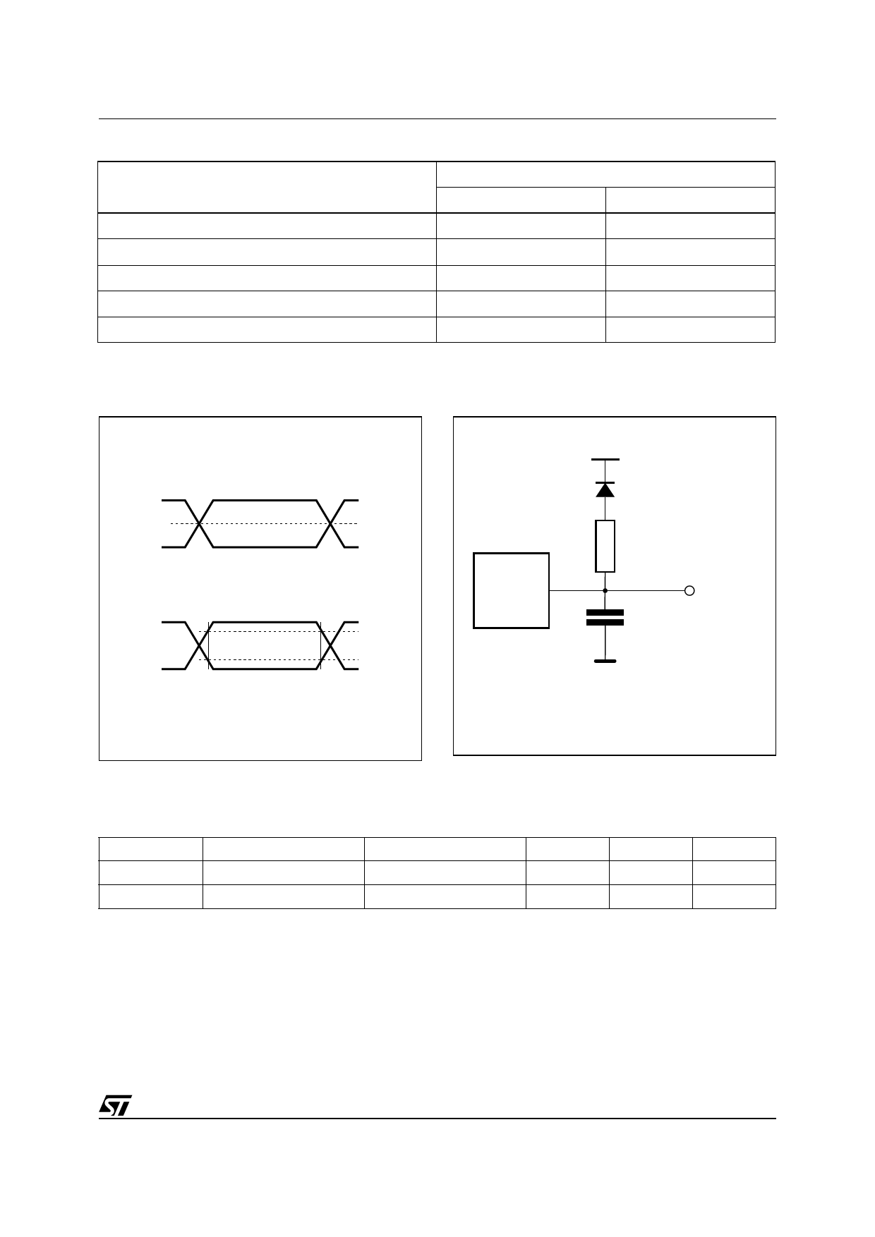
Table 8. AC Measurement Conditions
Parameter
AC Test Conditions
Load Capacitance (CL)
Input Rise and Fall Times
Input Pulse Voltages
Input and Output Timing Ref. Voltages
M29F010B
45
High Speed
30pF
≤10ns
0 to 3V
1.5V
M29F010B
70 / 90 / 120
Standard
100pF
≤10ns
0.45 to 2.4V
0.8V and 2V
Figure 6. AC Testing Input Output Waveform
High Speed
3V
0V
Standard
2.4V
0.45V
1.5V
2.0V
0.8V
AI01275B
Figure 7. AC Testing Load Circuit
1.3V
1N914
DEVICE
UNDER
TEST
3.3kΩ
OUT
CL = 30pF or 100pF
CL includes JIG capacitance
AI03027
Table 9. Capacitance
(TA = 25 °C, f = 1 MHz)
Symbol
Parameter
CIN
Input Capacitance
COUT
Output Capacitance
Note: Sampled only, not 100% tested.
Test Condition
VIN = 0V
VOUT = 0V
Min
Max
Unit
6
pF
12
pF
11/20
Share Link: 