EL2257CS 데이터 시트보기 (PDF) - Elantec -> Intersil
부품명
상세내역
제조사
EL2257CS Datasheet PDF : 21 Pages
| |||
EL2257C/EL2357C
125 MHz Single Supply, Clamping Op Amps
required to keep the junction temperature below abso-
lute maximum when an output is shorted indefinitely.
Power Dissipation
With the high output drive capability of the
EL2257C/EL2357C, it is possible to exceed the 150°C
Absolute Maximum junction temperature under certain
load current conditions. Therefore, it is important to cal-
culate the maximum junction temperature for the
application to determine if power-supply voltages, load
conditions, or package type need to be modified for the
EL2257C/EL2357C to remain in the safe operating area.
The maximum power dissipation allowed in a package is
determined by:
PDMAX = T----J---M-----A----X---θ--–-J---A-T----A----M-----A----X--
where:
• TJMAX = Maximum Junction Temperature
• TAMAX = Maximum Ambient Temperature
• θJA = Thermal Resistance of the Package
• PDMAX = Maximum Power Dissipation in the
Package.
The maximum power dissipation actually produced by
an IC is the total quiescent supply current times the total
power supply voltage, plus the power in the IC due to the
load, or:
PDMAX
=
N
×
VS
×
ISM
A
X
+
(VS
–
VOUT)
×
V-----O----U----T--
RL
where:
• N = Number of amplifiers
• VS = Total Supply Voltage
• ISMAX = Maximum Supply Current per amplifier
• VOUT = Maximum Output Voltage of the Application
• RL = Load Resistance tied to Ground
If we set the two PDMAX equations, [1] and [2], equal to
each other, and solve for VS, we can get a family of
curves for various loads and output voltages according
to:
VS = -R---------L--------×----------(------T--------J----NM----(----I--A--×--S----X----θ×------J--–--RA------T--L------A--)------M+----------VA--------X--O--------)U---+-T----(---V----O----U----T----)--2--
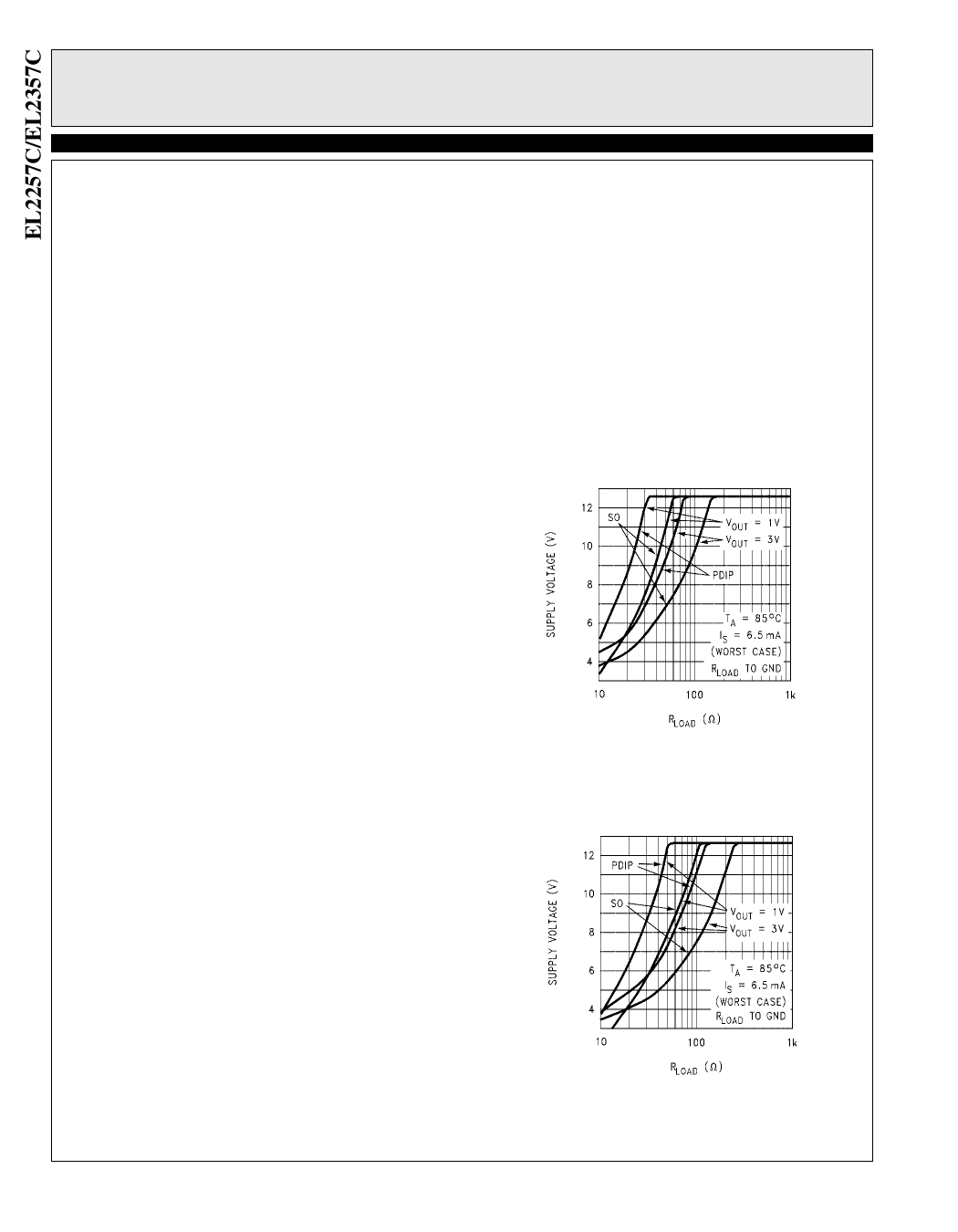
Figures 11 and 12 below show total single supply volt-
age VS vs. RL for various output voltage swings for the
PDIP and SOIC packages. The curves assume WORST
CASE conditions of TA = +85°C and IS = 6.5 mA per
amplifier.
EL2257 Single Supply Voltage
vs. RLoad for Various
VOUT and Packages
Figure 11.
EL2357 Single Supply Voltage
vs. RLoad for Various
VOUT and Packages
Figure 12.
18
Share Link: 