EL2360CS 데이터 시트보기 (PDF) - Elantec -> Intersil
부품명
상세내역
제조사
EL2360CS Datasheet PDF : 16 Pages
| |||
EL2360C
Triple 130 MHz Current Feedback Amplifier
Applications Information Contd
If we set the two PDMAX equations 1 and 2
equal to each other and solve for VS we can get a
family of curves for various loads and output
voltages according to 3
RL (TJMAX b TAMAX)
N iJA
a (VOUT)2
VS e
(IS RL) a VOUT
3
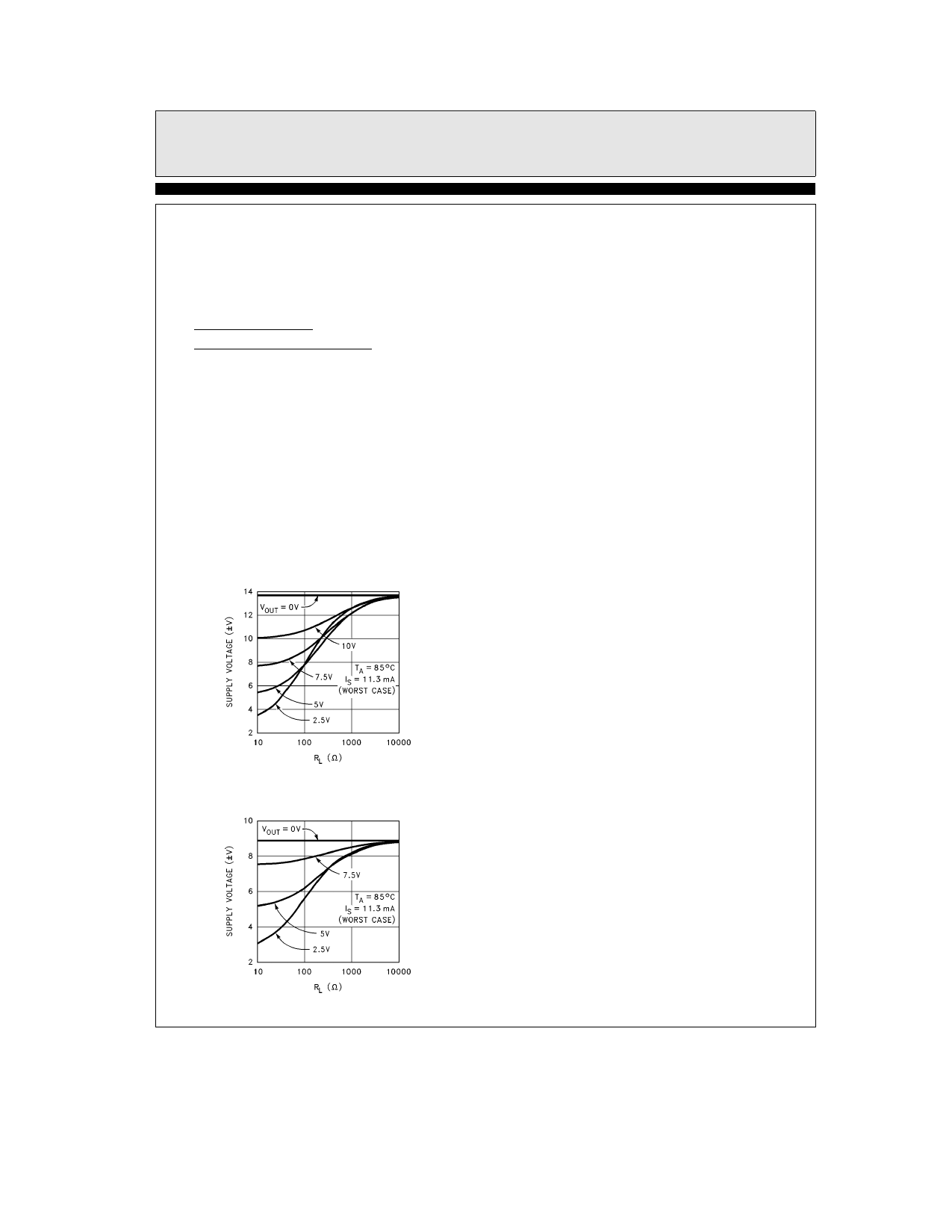
The figures below show total supply voltage VS
vs RL for various output voltage swings for the
PDIP and SOIC packages The curves assume
WORST CASE conditions of TA e a85 C and
IS e 11 3 mA per amplifier The curves do not
include heat removal or forcing air or the simple
fact that the package will be attached to a circuit
board which can also provide some form of heat
removal Larger temperature and voltage ranges
are possible with heat removal and forcing air
past the part
Supply Voltage vs RL
for Various VOUT (PDIP Package)
Current Limit
The EL2360C has internal current limits that
protect the circuit in the event of an output being
shorted to ground This limit is set at 100 mA
nominally and reduces with the junction temper-
ature At TJ e 150 C the current limits at about
65 mA If any one output is shorted to ground
the power dissipation could be well over 1W and
much greater if all outputs are shorted Heat re-
moval is required in order for the EL2360C to
survive an indefinite short
Driving Cables and Capacitive Loads
When used as a cable driver double termination
is always recommended for reflection-free per-
formance For those applications the back-termi-
nation series resistor will de-couple the EL2360C
from the cable and allow extensive capacitive
drive However other applications may have
high capacitive loads without a back-termination
resistor In these applications a small series resis-
tor (usually between 5X and 50X) can be placed
in series with the output to eliminate most peak-
ing The gain resistor (RG) can then be chosen to
make up for any gain loss which may be created
by this additional resistor at the output In many
cases it is also possible to simply increase the val-
ue of the feedback resistor (RF) to reduce the
peaking
2360 – 12
Supply Voltage vs RL
for Various VOUT (SOIC Package)
2360 – 13
13
Share Link: 