24C64 데이터 시트보기 (PDF) - STMicroelectronics
부품명
상세내역
제조사
24C64 Datasheet PDF : 45 Pages
| |||
Instructions
5
Instructions
M24C64-W M24C64-R M24C64-F
5.1
Write operations
Following a Start condition the bus master sends a device select code with the R/W bit (RW)
reset to 0. The device acknowledges this, as shown in Figure 9, and waits for two address
bytes. The device responds to each address byte with an acknowledge bit, and then waits
for the data byte.
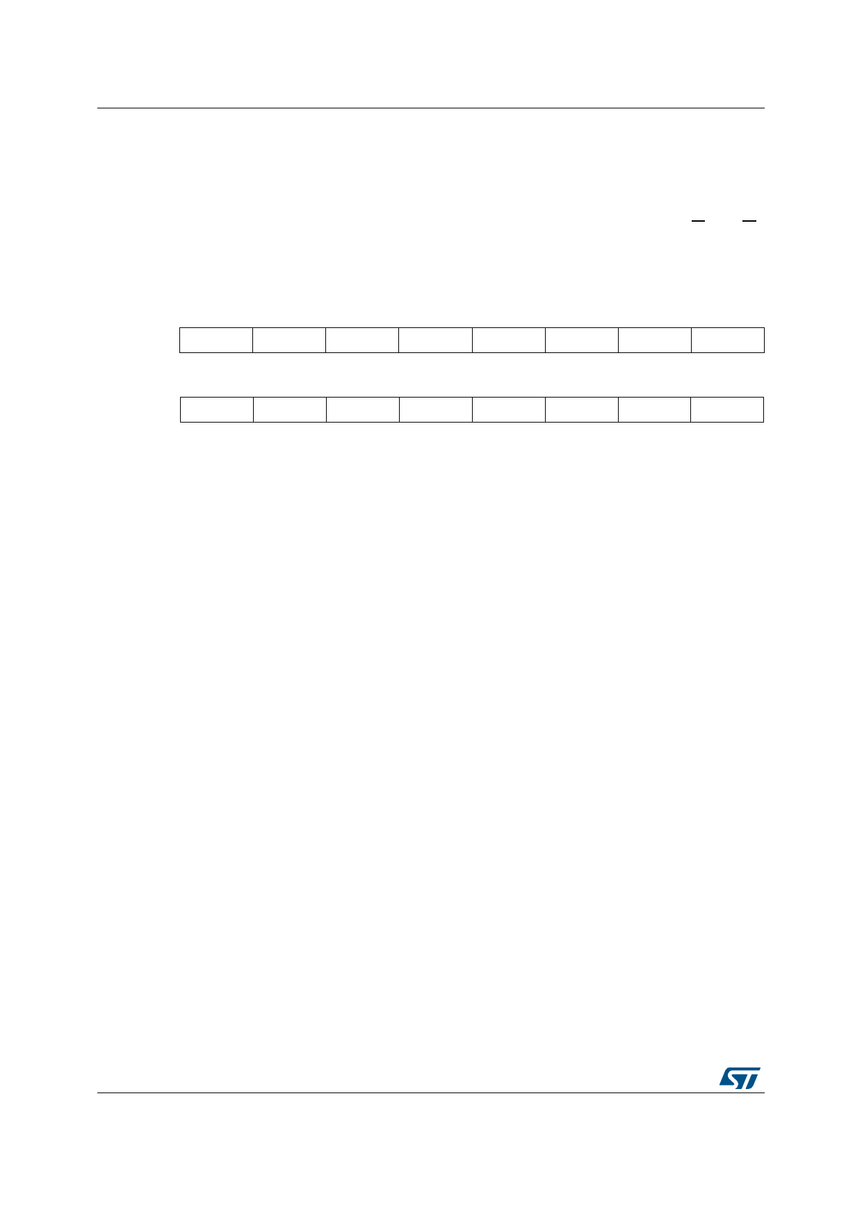
Table 3. Most significant address byte
A15
A14
A13
A12
A11
A10
A9
A8
Table 4. Least significant address byte
A7
A6
A5
A4
A3
A2
A1
A0
When the bus master generates a Stop condition immediately after a data byte Ack bit (in
the “10th bit” time slot), either at the end of a Byte Write or a Page Write, the internal Write
cycle tW is triggered. A Stop condition at any other time slot does not trigger the internal
Write cycle.
After the Stop condition and the successful completion of an internal Write cycle (tW), the
device internal address counter is automatically incremented to point to the next byte after
the last modified byte.
During the internal Write cycle, Serial Data (SDA) is disabled internally, and the device does
not respond to any requests.
If the Write Control input (WC) is driven High, the Write instruction is not executed and the
accompanying data bytes are not acknowledged, as shown in Figure 10.
14/45
DocID16891 Rev 30
Share Link: 