IMC020FLSA-ET15 데이터 시트보기 (PDF) - Intel
부품명
상세내역
제조사
IMC020FLSA-ET15 Datasheet PDF : 39 Pages
| |||
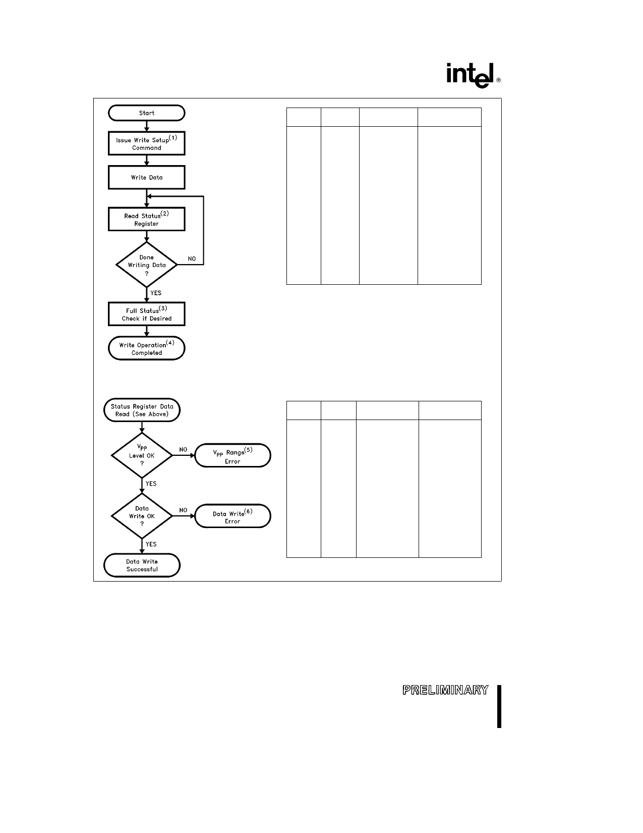
SERIES 2 FLASH MEMORY CARDS
Bus
Operation
Command
x8 Mode
x16 Mode
Write
Write
Write Setup
Data Write
Data e 40H
Address e Byte
Within Card to be
Written
Data to be Written
Address e Byte
Within Card to be
Written
Data e 4040H
Address e Word
Within Card to be
Written
Data to be Written
Address e Word
Within Card to be
Written
Read
Defaults to Status Register
Device Sta- Data Toggle OE
tus Register CE1 or CE2 to
Read Mode update Status
Register
Status Register
Data Toggle OE or
(CE1 and CE2 )
to update Status
Registers
Standby
Check SR Bit 7
1 e Ready
0 e Busy
Check SR Bits
7 and 15
1 e Ready
0 e Busy
290434 – 17
FULL STATUS CHECK
PROCEDURE
Bus
Operation
Command
x8 Mode
x16 Mode
Standby
Check SR Bit 3
1 e VPP Detected
Low
Check SR Bits
3 and 11
1 e VPP Detected
Low
Standby
Check SR Bit 4
Check SR Bits
1 e Data Write Error
4 and 12
1 e Data Write Error
290434 – 18
Figure 13 Device-Level Automated Write Algorithm
NOTES
1 Repeat for subsequent data writes
2 In addition the card’s READY-BUSY STATUS REGISTER or the RDY BSY pin may be used
3 Full device-level status check can be done after each data write or after a sequence of data writes
4 Write FFH (or FFFFH) after the last data write operation to reset the device(s) to Read Array Mode
5 If a data write operation fails due to a low VPP (setting SR Bit 3) the Clear Status Register command MUST be issued
before further attempts are allowed by the Write State Machine
6 If a data write operation fails during a multiple write sequence SR Bit 4 (Write Status) will not be cleared until the
Command User Interface receives the Clear Status Register command
20
Share Link: 