BU-61582 데이터 시트보기 (PDF) - Unspecified
부품명
상세내역
제조사
BU-61582 Datasheet PDF : 48 Pages
| |||
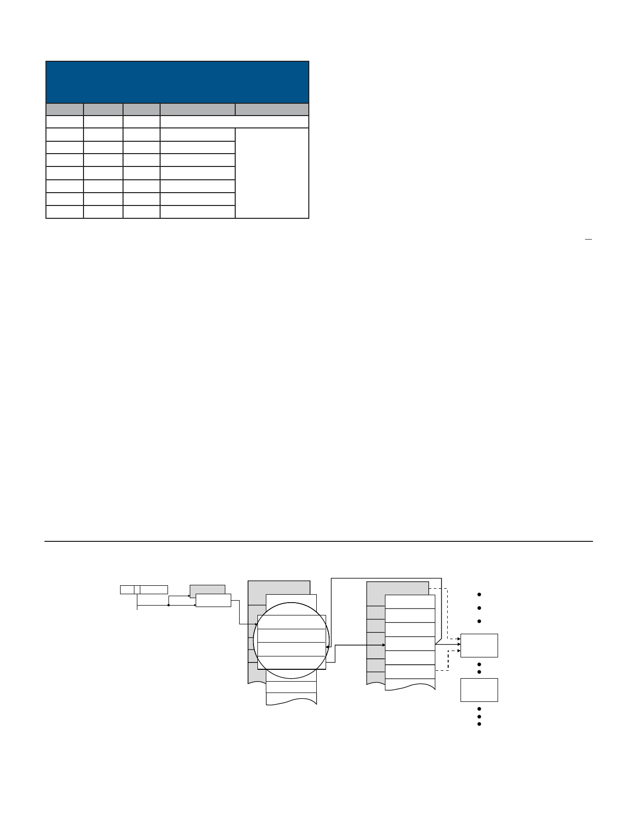
TABLE 30. SUBADDRESS CONTROL WORD
MEMORY MANAGEMENT SUBADDRESS BUFFER
SCHEME
MM2
0
0
0
0
MM1
0
0
1
1
MM0
0
1
0
1
DESCRIPTION
COMMENT
Single Message or Double Buffered
128-Word
256-Word
Circular Buffer of
Specified Size
512-Word
1
0
0
1024-Word
1
0
1
2048-Word
1
1
0
4096-Word
1
1
1
8192-Word
there are three possible memory management schemes: (1) sin-
gle message; (2) double buffered; and (3) circular buffer. For
each transmit, receive and broadcast subaddress, there are two
interrupt conditions programmable by the respective
Subaddress Control Word: (1) after every message to the sub-
address; (2) after a circular buffer rollover. An additional table in
RAM may be used to enable interrupts following selected mode
code messages.
When using the circular buffer scheme for a given subaddress,
the size of the circular buffer is programmable by three bits of the
Subaddress Control Word (see TABLE 30). The options for cir-
cular buffer size are 128, 256, 512, 1024, 2048, 4096, and 8192
Data Words.
SINGLE MESSAGE MODE
FIGURE 5 illustrates the RT Single Message memory manage-
ment scheme. When operating the BU-61582 in its “AIM-HY”
(default) mode, the Single Message scheme is implemented for
all transmit, receive, and broadcast subaddresses. In the Single
Message mode (also in the Double Buffer and Circular Buffer
modes), there is a global double buffering scheme, controlled by
bit 13 of Configuration Register #1. This selects from between
the two sets of the various data structures shown in the figure:
the Stack Pointers (fixed addresses), Descriptor Stacks (user
defined addresses), RT Lookup Tables (fixed addresses), and
RT Data Word blocks (user defined addresses). FIGURES 5, 6,
and 7 delineate the “active” and ”nonactive” areas by the non-
shaded and shaded areas, respectively.
As shown, the SP’ACE stores the Command Word from each
message received, in the fourth location within the message
descriptor (in the stack) for the respective message. The T/R
bit, subaddress field, and (optionally) broadcast/own address,
index into the active area Lookup Table, to locate the data block
pointer for the current message. The BU-61582 RT memory
management logic then accesses the data block pointer to
locate the starting address for the Data Word block for the cur-
rent message. The maximum size for an RT Data Word block is
32 words.
For a particular subaddress in the Single Message mode, there
is overwriting of the contents of the data blocks for receive/broad-
cast subaddresses – or overreading, for transmit subaddresses.
In the single message mode, it is possible to access multiple
data blocks for the same subaddress. This, however, requires the
intervention of the host processor to update the respective
Lookup Table pointer. To implement a data wraparound subad-
dress, as required by Notice 2 of MIL-STD-1553B, the Single
Message scheme should be used for the wraparound subad-
dress. Notice 2 recommends subaddress 30 as the wraparound
subaddress.
CONFIGURATION
REGISTER
15 13
0
STACK
POINTERS
DESCRIPTOR
STACKS
LOOK-UP TABLE
(DATA BLOCK ADDR)
DATA
BLOCKS
CURRENT
AREA B/A
BLOCK STATUS WORD
TIME TAG WORD
DATA BLOCK POINTER
RECEIVED COMMAND
WORD
LOOK-UP
TABLE ADDR
(See note)
DATA BLOCK
DATA BLOCK
Note: Lookup table is not used for mode commands when enhanced mode codes are enabled.
FIGURE 5. RT MEMORY MANAGEMENT: SINGLE MESSAGE MODE
Data Device Corporation
www.ddc-web.com
17
BU-61582
M-08/04-0
Share Link: 