LH1687 데이터 시트보기 (PDF) - Sharp Electronics
부품명
상세내역
제조사
LH1687 Datasheet PDF : 21 Pages
| |||
LH1687
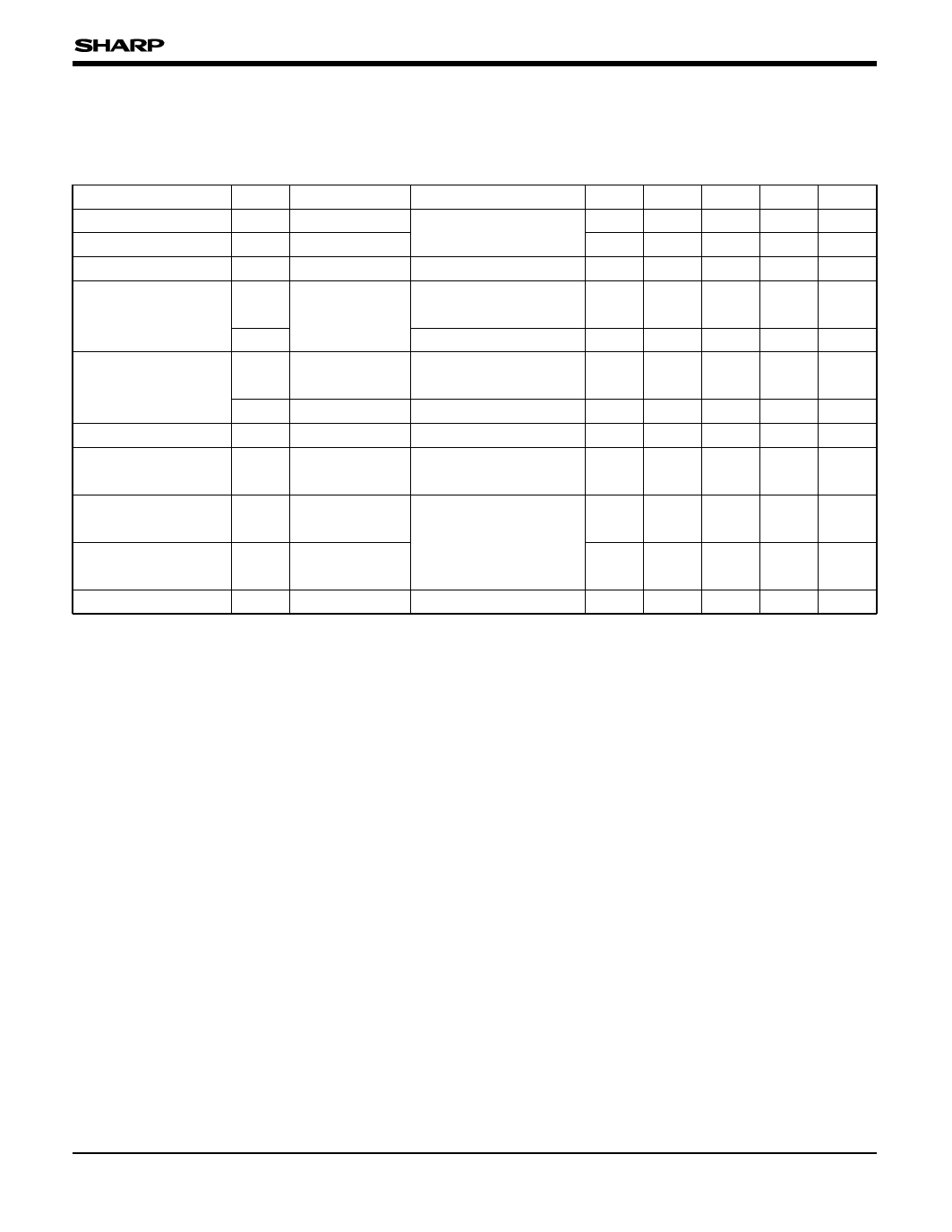
ELECTRICAL CHARACTERISTICS
DC Characteristics
(Unless otherwise specified, GNDL = GNDA = 0 V, VCCL = +3.3 V, VCCA = +5.0 V, TOPR = –30 to +85 ˚C)
PARAMETER SYMBOL CONDITIONS APPLICABLE PINS MIN. TYP. MAX. UNIT. NOTE
Input "Low" voltage
VIL
CK, CTR, SPIO, SPOI, 0
0.3VCCL V
Input "High" voltage
Input voltage
VIHL
VINA
MODE, RL, SAM, PS 0.7VCCL
VA, VB, VC
0
VCCL V
VCCA V
IIL1
Input "Low" current
VIN = 0 V
CK, CTR, SPIO, SPOI,
MODE, VA, VB, VC
10 µA
IIL2
RL, SAM, PS
CK, CTR, SPIO, SPOI,
IIHL
VIN = VCCL
Input "High" current
MODE, RL, SAM, PS
400 µA
10 µA
IIHA
VIN = VCCA
VA, VB, VC
10 µA
Dynamic range
Deviations between
output voltage pins
Vp-p
VOD
VA, VB, VC
0.1
OS1-OS240
–20
VCCA – 0.1 V
20 mV
1
Supply current
(In operation mode)
Supply current
(In power save mode)
ICCA1
ICCA2
VCCA
6.0
mA
2
100 µA
3
Supply current
ICCL1
VCCL
1.5
mA
2
NOTES :
1. Start signal :
Cycle tSP = 63.5 µs, "H" period width tWSP = 80 ns.
CTR signal :
Cycle tCTR = 127.0 µs, "H" period width tWCTR = 63.5 µs.
Change from "H" to "L" or "L" to "H" is synchronized with
start pulse during blanking period.
CK signal :
Frequency fCK = 12.5 MHz (duty = 50%)
VA = VB = VC = 0.1 V to VCCA – 0.1 V
Connect all other pins to high level.
Voltage difference between the average voltage of all
OS output pins in the chip and the output voltage of
each OS output pin. TA = 25 °C
2. Start signal :
Cycle tSP = 63.5 µs, "H" period width tWSP = 80 ns.
CTR signal :
Cycle tCTR = 127.0 µs, "H" period width tWCTR = 63.5 µs.
Change from "H" to "L" or "L" to "H" is synchronized with
start pulse during blanking period.
CK signal :
Frequency fCK = 12.5 MHz (duty = 50%)
Connect VA, VB, and VC pins to VCCA.
Connect all other pins to high level.
3. Start signal :
Cycle tSP = 63.5 µs, "H" period width tWSP = 80 ns.
CTR signal :
Cycle tCTR = 127.0 µs, "H" period width tWCTR = 63.5 µs.
Change from "H" to "L" or "L" to "H" is synchronized with
start pulse during blanking period.
CK signal :
Frequency fCK = 12.5 MHz (duty = 50%)
Pin to be set to GND : PS
Connect VA, VB, and VC pins to VCCA.
Connect all other pins to high level.
19
Share Link: 