AD8698 데이터 시트보기 (PDF) - Analog Devices
부품명
상세내역
제조사
AD8698 Datasheet PDF : 20 Pages
| |||

AD8698
LOW NOISE APPLICATIONS
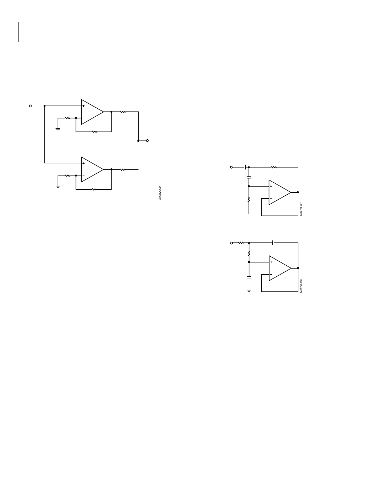
In some applications, it is critical to minimize the noise, and
although the AD8698 has a low noise of typically 8 nV/√Hz at
1 kHz, paralleling the two amplifiers within the same package
reduces the total noise referred to the input to approximately
5.5 nV/√Hz. This simple technique is depicted in Figure 55.
VIN
V+
V–
R1
1kΩ
R3
100Ω
R2
10kΩ
VOUT
V–
V+
R3
1kΩ
R5
100Ω
R4
10kΩ
Figure 55. Paralleling Amplifiers
DRIVING ADCs
The AD8698 can drive extremely heavy capacitive loads
without any compensation. Sometimes capacitors are placed at
the output of the amplifier to absorb transient currents while
the op amp is interfaced with the ADC. Most op amps need a
small resistor with the output to isolate the load capacitance.
This results in a loss of bandwidth and slows the amplifier
down substantially. However, the AD8698 maintains a unity
gain bandwidth of 1 MHz with loads of up to 1 nF, as shown in
Figure 52.
USING THE AD8698 IN ACTIVE FILTER DESIGNS
The AD8698 is recommended for unity gain filter designs with
a corner frequency of up to 100 kHz, one tenth of the op amp’s
unity gain bandwidth.
If a higher gain is desired, the corner frequency should be
chosen accordingly. For example, if the amplifier is configured
with a gain of 10, the corner frequency of the filter should not
be more than 10 kHz.
An example of an active filter is the Sallen Key. This topology
gives the user the flexibility of implementing a low-pass or a
high-pass filter by simply interchanging the resistors and the
capacitors.
In the high-pass filter of Figure 56, the damping factor Q is set
to 1/√2 for a maximally flat response (Butterworth).
The gain is unity and the bandwidth is 10 kHz with the values
shown.
C1
1nF
VIN
C2
1nF
R1
11kΩ
V+
R2
V–
22kΩ
Figure 56. Two Pole High-Pass Filter
R1
C1
11kΩ
2nF
VIN
R2
11kΩ
V+
V–
C2
1nF
Figure 57. Two Pole Low-Pass Filter
The circuit of Figure 57 has a bandwidth of 10 kHz and a
maximally flat response. In this case, the damping factor is
controlled by the ratio of the capacitors and the gain is unity.
Rev. 0 | Page 16 of 20