10N120BND 데이터 시트보기 (PDF) - Fairchild Semiconductor
부품명
상세내역
제조사
10N120BND
Fairchild Semiconductor

10N120BND Datasheet PDF : 8 Pages
| |||
HGTG10N120BND
Electrical Specifications TC = 25oC, Unless Otherwise Specified (Continued)
PARAMETER
Current Turn-On Delay Time
Current Rise Time
Current Turn-Off Delay Time
Current Fall Time
Turn-On Energy
Turn-Off Energy (Note 3)
Diode Forward Voltage
Diode Reverse Recovery Time
Thermal Resistance Junction To Case
SYMBOL
td(ON)I
trI
td(OFF)I
tfI
EON
EOFF
V EC
t rr
RθJC
TEST CONDITIONS
IGBT and Diode at TJ = 150oC
ICE = 10A
VCE = 960V
VGE = 15V
RG = 10Ω
L = 2mH
Test Circuit (Figure 20)
IEC = 10A
IEC = 10A, dIEC/dt = 200A/µs
IEC = 1A, dIEC/dt = 200A/µs
IGBT
Diode
MIN TYP MAX UNITS
-
21
25
ns
-
11
15
ns
-
190
250
ns
-
140
200
ns
-
1.75
2.3
mJ
-
1.1
1.4
mJ
-
2.55
3.2
V
-
57
70
ns
-
32
40
ns
-
-
0.42
oC/W
-
-
1.25
oC/W
NOTE:
3. Turn-Off Energy Loss (EOFF) is defined as the integral of the instantaneous power loss starting at the trailing edge of the input pulse and ending
at the point where the collector current equals zero (ICE = 0A). All devices were tested per JEDEC Standard No. 24-1 Method for Measurement
of Power Device Turn-Off Switching Loss. This test method produces the true total Turn-Off Energy Loss.
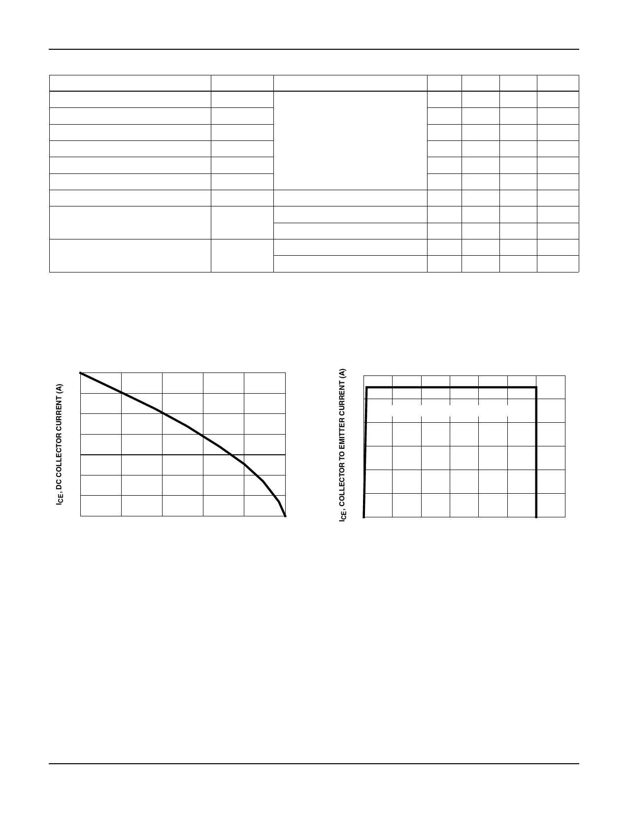
Typical Performance Curves Unless Otherwise Specified
35
VGE = 15V
30
25
20
15
10
5
0
25
50
75
100
125
150
TC, CASE TEMPERATURE (oC)
FIGURE 1. DC COLLECTOR CURRENT vs CASE
TEMPERATURE
60
50
TJ = 150oC, RG = 10Ω, VG = 15V, L = 400µH
40
30
20
10
0
0
200 400 600 800 1000 1200 1400
VCE, COLLECTOR TO EMITTER VOLTAGE (V)
FIGURE 2. MINIMUM SWITCHING SAFE OPERATING AREA
©2001 Fairchild Semiconductor Corporation
HGTG10N120BND Rev. B
Share Link: