DS2741N 데이터 시트보기 (PDF) - Maxim Integrated
부품명
상세내역
제조사
DS2741N Datasheet PDF : 10 Pages
| |||
Current Monitor and Accumulator with
Integrated Sense Resistor
Registers
The DS2741 has 2-byte registers for current measure-
ment and accumulation. When the MSB of a 2-byte reg-
ister is read, both the MSB and LSB are latched and
held for the duration of the read data command to pre-
vent updates during the read and ensure synchroniza-
tion between the two register bytes. For consistent
results, always read the MSB and the LSB of a 2-byte
register during the same read data command sequence.
Table 1. Register Map
ADDRESS
(HEX)
DESCRIPTION
00h to 0Fh Reserved
10h and 11h Current Accumulator Register
12h and 13h Reserved
14h
Temperature Register
15h
Reserved
16h and 17h Current Register
18h to FFh Reserved
READ/WRITE
—
R/W
—
R
—
R
—
I2C Bus Interface
I2C Definitions
The following terminology is commonly used to
describe I2C data transfers.
Master Device: The master device controls the slave
devices on the bus. The master device generates
SCL clock pulses and START and STOP conditions.
Slave Devices: Slave devices send and receive
data at the master’s request.
Bus Idle or Not Busy: Time between STOP and
START conditions when both SDA and SCL are inac-
tive and in their logic-high states. When the bus is idle
it often initiates a low-power mode for slave devices.
START Condition: A START condition is generated
by the master to initiate a new data transfer with a
slave. Transitioning SDA from high to low, while SCL
remains high, generates a START condition. See
Figure 4 for applicable timing.
STOP Condition: A STOP condition is generated by
the master to end a data transfer with a slave.
Transitioning SDA from low to high, while SCL
remains high, generates a STOP condition. See
Figure 4 for applicable timing.
Repeated START Condition: The master can use a
repeated START condition at the end of one data
transfer to indicate that it will immediately initiate a
new data transfer following the current one.
Repeated STARTs are commonly used during read
operations to identify a specific memory address to
begin a data transfer. A repeated START condition
is issued identically to a normal START condition.
See Figure 4 for applicable timing.
Bit Write: Transitions of SDA must occur during the
low state of SCL. The data on SDA must remain
valid and unchanged during the entire high pulse of
SCL plus the setup and hold-time requirements (see
Figure 4). Data is shifted into the device during the
rising edge of the SCL.
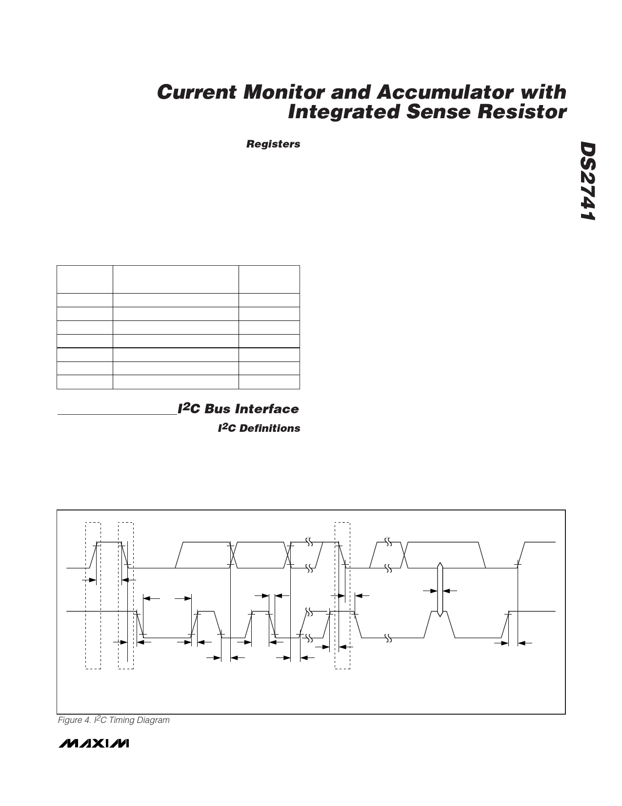
SDA
tBUF
tLOW
tF
tHD:STA
tSP
SCL
tHD:STA
STOP
START
tHIGH
tR
tHD:DAT
tSU:DAT
NOTE: TIMING IS REFERENCED TO VIL(MAX) AND VIH(MIN).
Figure 4. I2C Timing Diagram
tSU:STA
REPEATED
START
tSU:STO
_______________________________________________________________________________________ 7
Share Link: 