LTC6801HG-PBF 데이터 시트보기 (PDF) - Linear Technology
부품명
상세내역
제조사
LTC6801HG-PBF Datasheet PDF : 28 Pages
| |||
LTC6801
APPLICATIONS INFORMATION
In the absence of external noise filtering, the input resis-
tance of the ADC will cause open wires to produce a near
zero reading. This reading will cause an undervoltage
failure during the normal measurement cycle.
Some applications may include external noise filtering to
improve the quality of the voltage comparisons. When
an RC network is used to filter noise, an open wire may
not produce a zero reading because the comparator input
resistance is too large to discharge the capacitors on the
input pin. Charge may build up on the open pin during
successive measurement cycles to the extent that it could
indicate a valid cell voltage reading.
During each self test cycle, the LTC6801 will sink 100μA
to V– from each side of the cell being measured. The
undervoltage threshold is not checked during the self test
because the 100μA pull-down current would cause false
failures in some cases. If an input is open, this current will
discharge any filtering capacitors and cause the input to
float down to approximately 0.7V below the next lower cell
input. In most cases, the cell voltage of the cell above the
open input will exceed the overvoltage threshold and flag
a self test error. During the normal measurement cycle,
the LTC6801 will sink 1μA to V– from each side of the cell
being measured. If the cell voltages are low enough that
an open wire is not detected as an overvoltage during
self test, this current will cause the cell input to settle to
a voltage low enough to trigger an undervoltage condition
during the normal measurement cycle.
Note, an open cell connection may not be detected when
the UV = 0.766V setting is used. For all other UV settings,
an open cell connection will result in either a self test error
or no SOUT clock.
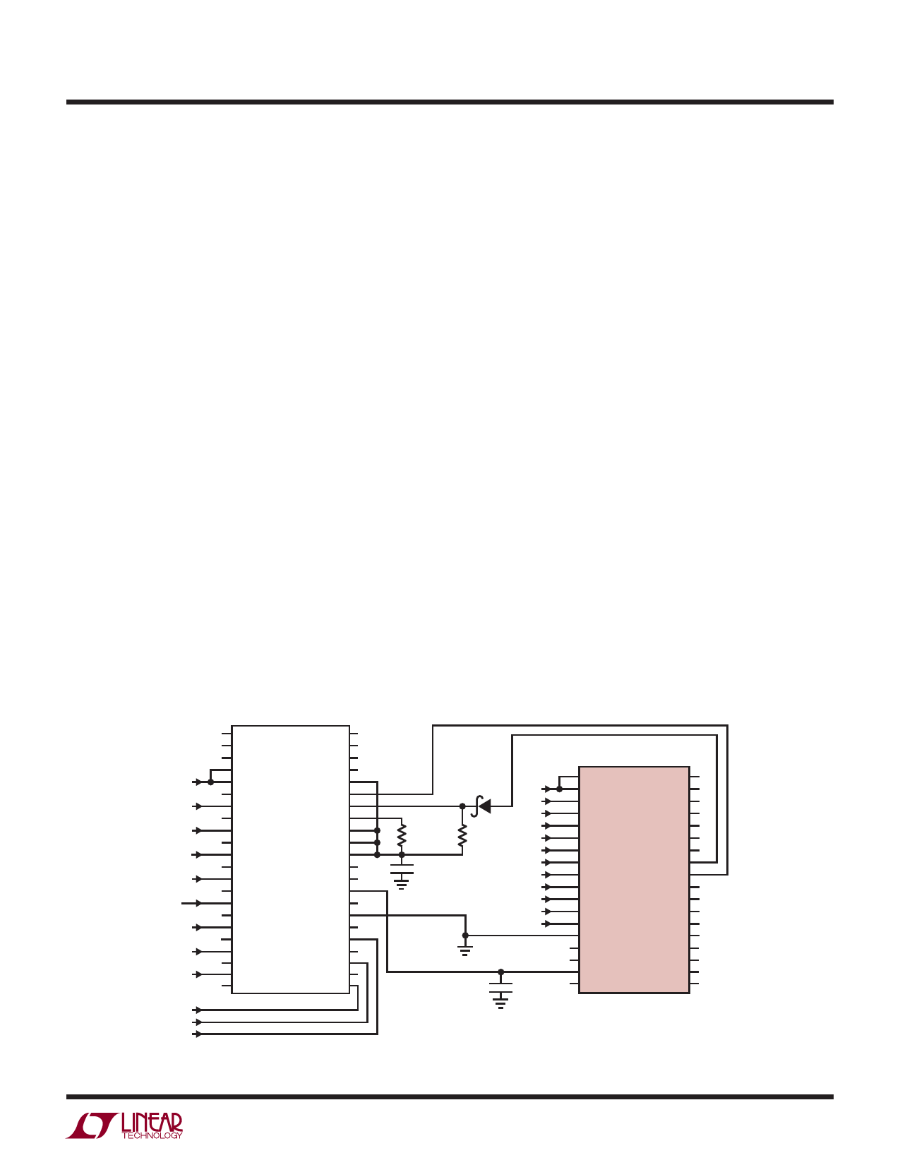
Using The LTC6801 with Other Battery Monitors
When used in combination with an LTC6802-1, it is possible
to check the LTC6801 self test result via the LTC6802-1 and
its isolated SPI. As shown in Figure 7, the SLTOK output
is tied to the GPIO2 pin on the LTC6802-1. SLTOK will
remain high as long as it is passing the self test. A self test
will occur automatically every 1024 measurement cycles
(17 seconds to 9 minutes, depending on measurement
duty cycle). A self test can be initiated by a falling edge
on SLT, via the LTC6802-1 GPIO1 line. A self test will start
after the current measurement cycle is complete, and the
SLTOK status will be valid when the self test completes.
The worst case delay before SLTOK is valid in continuous
monitor mode is approximately 15ms for the current cycle
to complete plus 17ms for the self test to complete.
The 6802-1 can measure the LTC6801 reference, which will
independently test the analog circuitry of the LTC6802.
CSBO
CSBI
SDOI
SDO
SCKO
SDI
V+
SCKI
C12
C12
VMODE
S12
GPIO2
C11
C11
GPIO1
S11
WDTB
C10
C10
MMB
S10 LTC6802-1 TOS
C9
C9
VREG
S9
VREF
C8
C8
VTEMP2
S8
VTEMP1
C7
C7
NC
S7
V–
C6
C6
S1
S6
C1
C5
C5
S2
S5
C2
C4
C4
S3
S4
C3
C3
C2
C1
IN
OUT
1M
1μF
CMPD6263 C12
C11
C10
C9
100k
C8
C7
C6
C5
C4
C3
C2
C1
VREF
1μF
V+
OV1
C12
OV0
C11
UV1
C10
UV0
C9
HYST
C8 LTC6801 CC1
C7
CC0
C6
SLT
C5
SLTOK
C4
DC
C3
EOUT
C2
EOUT
C1
SIN
V–
SIN
VTEMP1
VTEMP2
SOUT
SOUT
VREF
EIN
VREG
EIN
6801 F07
Figure 7. Interconnection of an LTC6802-1 and LTC6801 for Self Test.
6801fb
19
Share Link: 