MAC16CM 데이터 시트보기 (PDF) - ON Semiconductor
부품명
상세내역
제조사
MAC16CM Datasheet PDF : 6 Pages
| |||
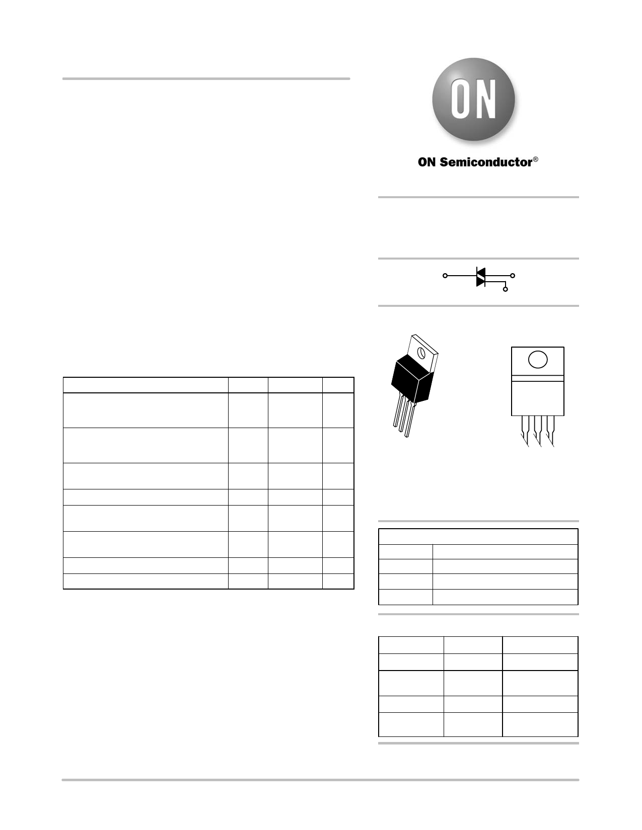
MAC16CM, MAC16CN
Triacs
Preferred Device
Silicon Bidirectional Thyristors
Designed primarily for full wave ac control applications, such as
motor controls, heating controls or dimmers; or wherever full−wave,
silicon gate−controlled devices are needed.
Features
• High Commutating di/dt and High Immunity to dV/dt @ 125°C
• Minimizes Snubber Networks for Protection
• Blocking Voltage to 800 Volts
• On-State Current Rating of 16 Amperes RMS
• High Surge Current Capability − 150 Amperes
• Industry Standard TO-220AB Package for Ease of Design
• Glass Passivated Junctions for Reliability and Uniformity
• Operational in Three Quadrants, Q1, Q2, and Q3
• Pb−Free Packages are Available*
MAXIMUM RATINGS (TJ = 25°C unless otherwise noted)
Rating
Symbol Value
Peak Repetitive Off-State Voltage (Note 1) VDRM,
(TJ = − 40 to 125°C)
MAC16CM
600
MAC16CN VRRM
800
On-State RMS Current
(Full Cycle Sine Wave 50 to 60 Hz;
TC = 80°C)
IT(RMS)
16
Peak Non-Repetitive Surge Current
(One Full Cycle, 60 Hz, TJ = 125°C)
ITSM
150
Circuit Fusing Consideration (t = 8.33 ms) I2t
93
Unit
V
A
A
A2sec
Peak Gate Power
(Pulse Width ≤ 1.0 ms, TC = 80°C)
PGM
20
W
Average Gate Power
(t = 8.3 ms, TC = 80°C)
PG(AV)
0.5
W
Operating Junction Temperature Range
TJ
−40 to +125 °C
Storage Temperature Range
Tstg −40 to +150 °C
Maximum ratings are those values beyond which device damage can occur.
Maximum ratings applied to the device are individual stress limit values (not
normal operating conditions) and are not valid simultaneously. If these limits are
exceeded, device functional operation is not implied, damage may occur and
reliability may be affected.
1. VDRM and VRRM for all types can be applied on a continuous basis. Blocking
voltages shall not be tested with a constant current source such that the
voltage ratings of the devices are exceeded.
*For additional information on our Pb−Free strategy and soldering details, please
download the ON Semiconductor Soldering and Mounting Techniques
Reference Manual, SOLDERRM/D.
© Semiconductor Components Industries, LLC, 2005
1
December, 2005 − Rev. 3
http://onsemi.com
TRIACS
16 AMPERES RMS
400 thru 800 VOLTS
MT2
MT1
G
MARKING
DIAGRAM
123
TO−220AB
CASE 221A−09
STYLE 4
MAC16CxG
AYWW
x = M or N
A = Assembly Location
Y = Year
WW = Work Week
G = Pb−Free Package
PIN ASSIGNMENT
1
Main Terminal 1
2
Main Terminal 2
3
Gate
4
Main Terminal 2
ORDERING INFORMATION
Device
Package
Shipping
MAC16CM
TO−220AB
50 Units / Rail
MAC16CMG
TO−220AB
(Pb−Free)
50 Units / Rail
MAC16CN
MAC16CNG
TO−220AB
TO−220AB
(Pb−Free)
50 Units / Rail
50 Units / Rail
Preferred devices are recommended choices for future use
and best overall value.
Publication Order Number:
MAC16C/D
Share Link: 