PCF2119AU-2 데이터 시트보기 (PDF) - Philips Electronics
부품명
상세내역
제조사
PCF2119AU-2 Datasheet PDF : 68 Pages
| |||
Philips Semiconductors
LCD controllers/drivers
Product specification
PCF2119X
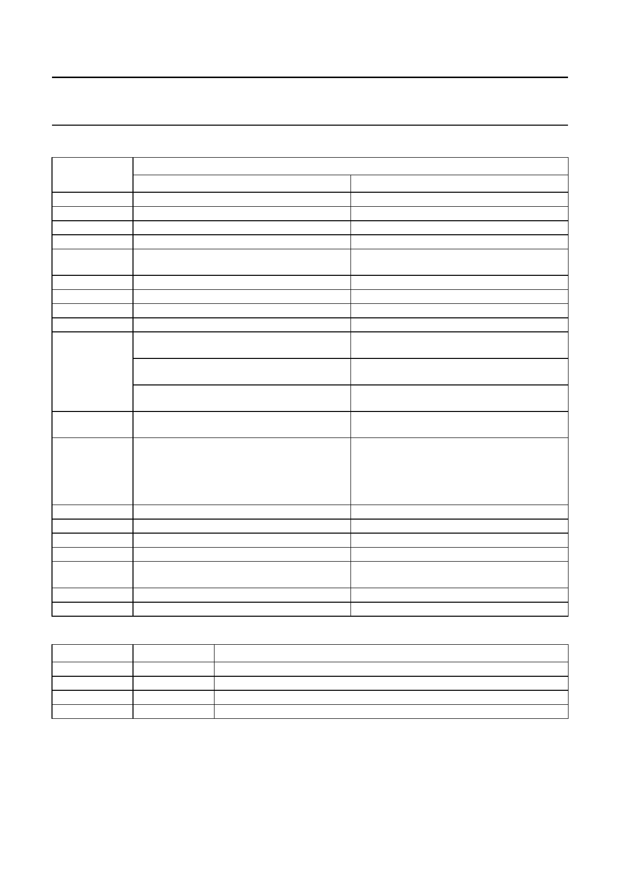
Table 7 Explanations of symbols used in Table 6
BIT
I/D
S
D
C
B
S/C
R/L
DL
H
L (no impact, if
M = 1 or SL = 1)
P
Q
IM
IB
DM
V
M (no impact, if
SL = 1)
SL
C0
STATE
LOGIC 0
LOGIC 1
decrement
display freeze
display off
cursor off
cursor character blink off: character at cursor
position does not blink
cursor move
left shift
4 bits
use basic instruction set
left/right screen: standard connection (as in
PCF2114)
1st 16 characters of 32: columns are from
1 to 80
2nd 16 characters of 32: columns are from
1 to 80
column data: left to right (as in PCF2116);
column data is displayed from 1 to 80
row data top to bottom (as in PCF2116):
row data is displayed from 1 to 16 and icon row
data in 17 and 18
in single line mode (SL = 1) row data is
displayed from 1 to 8 and icon row data in 17
character mode; full display
icon blink disabled
direct mode disable
set VA
1-line by 32 display
increment
display shift
display on
cursor on
cursor character blink on: character at cursor
position blinks
display shift
right shift
8 bits
use extended instruction set
left/right screen: mirrored connection (as in
PCF2116)
1st 16 characters of 32: columns are from
1 to 80
2nd 16 characters of 32: columns are from
80 to 1
column data: right to left; column data is
displayed from 80 to 1
row data bottom to top:
row data is displayed from 16 to 1 and icon row
data in 18 and 17
in single line mode (SL = 1) row data is
displayed from 8 to 1 and icon row data in 17
icon mode; only icons displayed
icon blink enabled
direct mode enable
set VB
2-line by 16 display
MUX 1 : 18 (1 × 32 or 2 × 16 character display) MUX 1 : 9 (1 × 16 character display)
last control byte; see Table 5
another control byte follows after data/command
Table 8 Explanation of TC1 and TC2 used in Table 6
TC1
TC2
DESCRIPTION(1)
0
0
VLCD temperature coefficient 0
1
0
VLCD temperature coefficient 1
0
1
VLCD temperature coefficient 2
1
1
VLCD temperature coefficient 3
Note
1. For values of the temperature coefficients, see Chapter 13
2003 Jan 30
25
Share Link: 