SI4113G-BM 데이터 시트보기 (PDF) - Silicon Laboratories
부품명
상세내역
제조사
SI4113G-BM
Silicon Laboratories

SI4113G-BM Datasheet PDF : 32 Pages
| |||
Si4133G
IFOUT
LMATCH
560 pF
50 Ω
Reference Frequency Amplifier
The Si4133G provides a reference frequency amplifier.
If the driving signal has CMOS levels it can be
connected directly to the XIN pin. Otherwise, the
reference frequency signal should be AC coupled to the
XIN pin through a 560 pF capacitor.
Power Down Modes
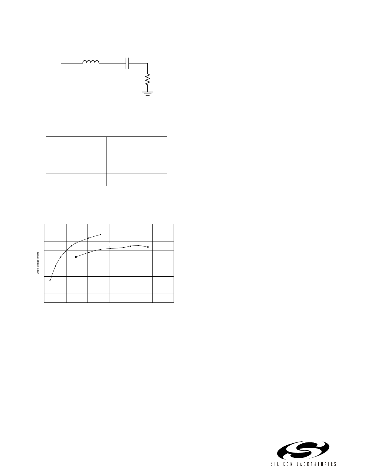
Figure 17. IFOUT 50 Ω Test Circuit
Table 8. LMATCH Values
Frequency
500–600 MHz
LMATCH
40 nH
600–800 MHz
27 nH
800–1 GHz
18 nH
The IF output level is dependent upon the load.
Figure 18 displays the output level versus load
resistance for a variety of output frequencies.
450
400
350
LPWR=0
300
LPWR=1
250
200
150
100
50
0
0
200
400
600
800
1000
1200
Load Resistance (Ω)
Figure 18. Typical IF Output Voltage vs. Load
Resistance at 550 MHz
Table 9 summarizes the power down functionality. The
Si4133G can be powered down by taking the PWDNB
pin low or by setting bits in the Power Down register
(Register 1). When the PWDNB pin is low, the Si4133G
will be powered down regardless of the Power Down
register settings. When the PWDNB pin is high, power
management is under control of the Power Down
register bits.
The reference frequency amplifier, IF, and RF sections
of the Si4133G circuitry can be individually powered
down by setting the Power Down register bits PDIB and
PDRB low, respectively. The reference frequency
amplifier will also be powered up if either of the PDRB
or PDIB bits are high. Also, setting the AUTOPDB bit to
1 in the Main Configuration register (Register 0) is
equivalent to setting both bits in the Power Down
register to 1. The serial interface remains available and
can be written in all power down modes.
Auxiliary Output (AUXOUT)
The signal appearing on AUXOUT is selected by setting
the AUXSEL bits in the Main Configuration register
(Register 0).
The LDETB signal can be selected by setting the
AUXSEL bits to 11. As discussed previously, this signal
can be used to indicate that the IF or RF PLL is about to
lose lock due to excessive ambient temperature drift and
should be re-tuned.
For resistive loads greater than 500 Ω the output level
saturates and the bias currents in the IF output amplifier
are higher than they need be. The LPWR bit in the Main
Configuration register (Register 0) can be set to 1 to
reduce the bias currents and therefore reduce the
power dissipated by the IF amplifier. For loads less than
500 Ω LPWR should be set to 0 to maximize the output
level.
18
Rev. 1.1
Share Link: