STK672-400C-E 데이터 시트보기 (PDF) - SANYO -> Panasonic
부품명
상세내역
제조사
STK672-400C-E Datasheet PDF : 19 Pages
| |||
STK672-400C-E
3. Calculating STK672-400C-E HIC Internal Power Loss
HIC internal loss calculation of STK672-400C-E
The internal average power loss in the excitation modes of STK672-400 is calculated as follows:
[Excitation modes]
2 phase excitation mode
2PdAV = (Vsat+Vdf)×0.5×CLOCK×IOH×t2+0.5×CLOCK×IOH× (Vsat×t1+Vdf×t3) --------------------------- (3-1)
1-2 phase excitation mode
1-2PdAV = (Vsat+Vdf)×0.25×CLOCK×IOH×t2+0.25×CLOCK×IOH× (Vsat×t1+Vdf×t3) ---------------------- (3-2)
W1-2 phase excitation mode
W1-2PdAV =0.64[(Vsat+Vdf)×0.25×CLOCK×IOH×t2+0.25×CLOCK×IOH× (Vsat×t1+Vdf×t3)] ------------- (3-3)
2W1-2 phase excitation mode
2W1-2PdAV =0.64[(Vsat+Vdf)×0.0625×CLOCK×IOH×t2+0.0625×CLOCK×IOH× (Vsat×t1+Vdf×t3)] ------ (3-4)
4W1-2 phase excitation mode
4W1-2PdAV =0.64[(Vsat+Vdf)×0.0625×CLOCK×IOH×t2+0.0625×CLOCK×IOH× (Vsat×t1+Vdf×t3)] ------ (3-5)
At motor hold
Hold PdAV = (Vsat+Vdf)×IOH---------------------------------------------------------------------------------------------- (3-6)
Note: 2-phase 100% conductance is assumed in Equation (3-6).
Vsat: Synthetic voltage of Ron voltage drop + Synthetic voltage of current detection resistance
Vdf: Synthetic voltage of FET body diode Vdf + Synthetic voltage of current detection resistance
CLOCK: Input clock CLK (reference frequency before splitting into four phases)
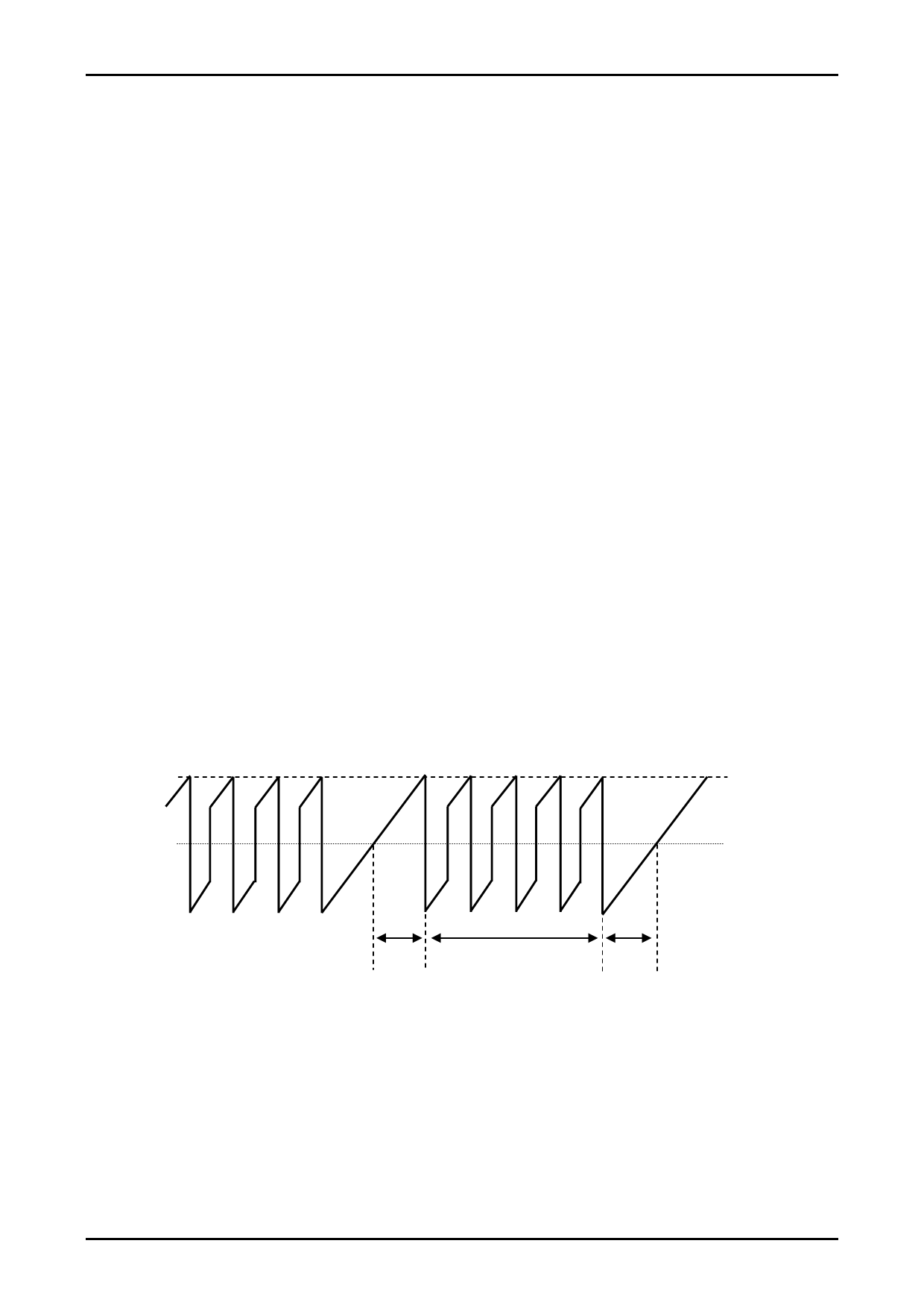
t1, t2, and t3 are waveforms shown in the following figure:
t1: Time till the winding current reaches the set value (IOH).
t2: Time for the constant-current control (PWM) region
t3: Time from the phase signal OFF up to regenerative consumption of the counter electromotive force
IOH
0A
t1
t2
t3
Motor COM Current Waveform Model
t1= (-L/(R+0.42)) ln (1-((R+0.42)/VCC1) ×IOH)) ---------------------------------------------------------------- (3-7)
t3= (-L/R) ln ((VCC1+0.9)/(IOH×R+VCC1+0.9)) ---------------------------------------------------------------- (3-8)
VCC1: Motor supply voltage (V)
L: Motor inductance (H)
R: Motor winding resistance (Ω)
IOH: Motor set output current crest value (A)
No.A2136-12/19
Share Link: 