HA13568AT 데이터 시트보기 (PDF) - Hitachi -> Renesas Electronics
부품명
상세내역
제조사
HA13568AT Datasheet PDF : 22 Pages
| |||
HA13568AT
Note:
1. The output saturation voltage is the sum of the upper and lower saturation voltages.
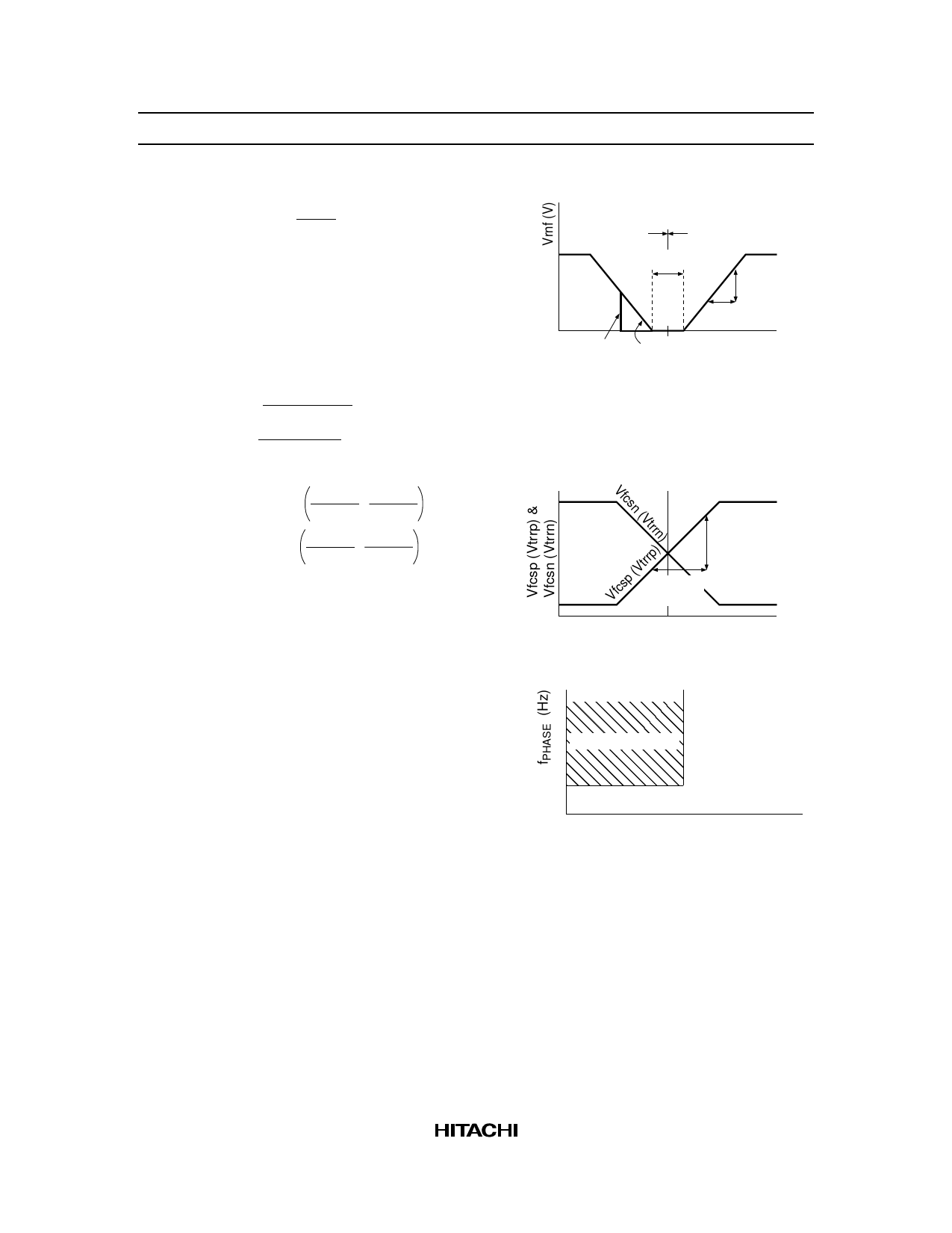
2. See figure 1. Where,
Gctl = 20 log
∆Vrnf
∆Vctl
Vspncl
Reverse
torque
Forward
torque
Vdzspn
∆Vrnf
Vref ∆Vctl
3. Where,
Vqfcs = Vfcsp + Vfcsn
2
Vqtrr = Vtrrp + Vtrrn
2
4. See figure 2. Where,
Figure 1
0 Reverse brake Short brake
Vctl (V)
Gvfcs = 20 log
∆Vfcsp
∆Vfcsin
∆Vfcsn
∆Vfcsin
Gvtrr = 20 log
∆Vtrrp
∆Vtrrin
∆Vtrrn
∆Vtrrin
∆Vfcsp
(∆Vtrrp)
∆Vfcsin
(∆Vtrrin)
0
Vref Vfcsin (Vtrrin)
Figure 2
5. The circuit operates in soft switching drive mode only when the control input (Vctl) is lower than
fCT2 and fPHASE is higher than the threshold voltage. See figure 3.
SOFT SW mode
, SWmode
fCT2
, , 0
Figure 3
SW mode
0.5V VCTL − REFIN
6. PHASE is output only when B-EMF exceeds the threshold voltage.
18
Share Link: 