M80C186 데이터 시트보기 (PDF) - Intel
부품명
상세내역
제조사
M80C186 Datasheet PDF : 59 Pages
| |||
M80C186
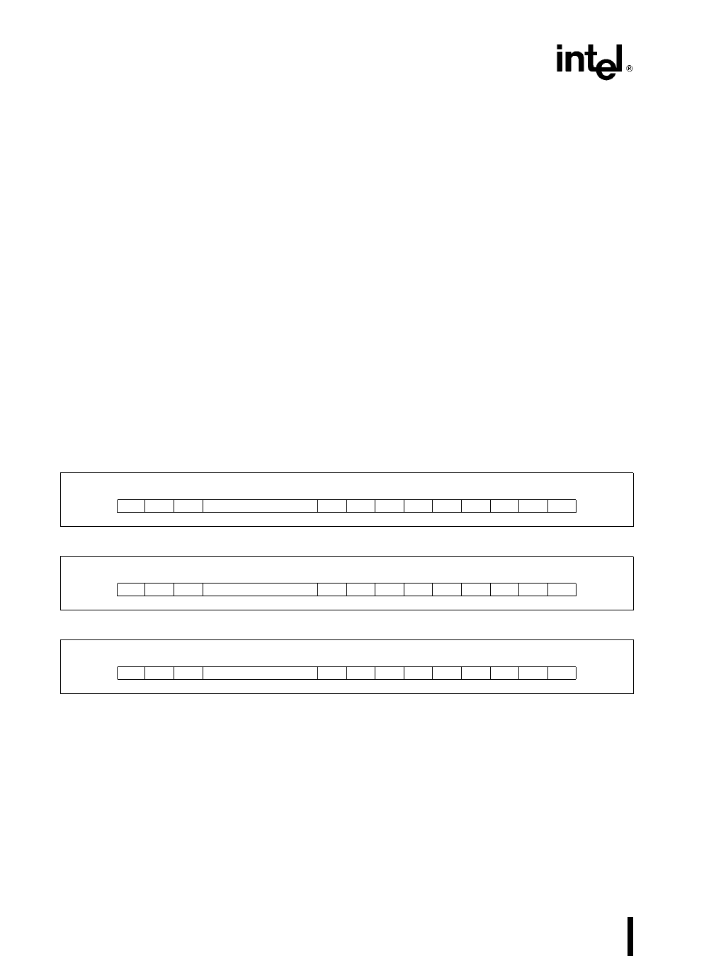
Interrupt Vector Register
This register provides the upper five bits of the inter-
rupt vector address The format of this register is
shown in Figure 38 The interrupt controller itself
provides the lower three bits of the interrupt vector
as determined by the priority level of the interrupt
request
The format of the bits in this register is
tx 5-bit field indicating the upper five bits of the
vector address
Priority-Level Mask Register
This register indicates the lowest priority-level inter-
rupt which will be serviced
The encoding of the bits in this register is
mx 3-bit encoded field indication priority-level val-
ue All levels of lower priority will be masked
Interrupt Controller and Reset
Upon RESET the interrupt controller will perform
the following actions
All SFNM bits reset to 0 implying Fully Nested
Mode
All PR bits in the various control registers set to 1
This places all sources at lowest priority (level
111)
All LTM bits reset to 0 resulting in edge-sense
mode
All Interrupt Service bits reset to 0
All Interrupt Request bits reset to 0
All MSK (Interrupt Mask) bits set to 1 (mask)
All C (Cascade) bits reset to 0 (non-cascade)
All PRM (Priority Mask) bits set to 1 implying no
levels masked
Initialized to master mode
Interrupt Status Register
This register is defined as in master mode except
that DHLT is not implemented (see Figure 27)
15 14 13
0
0
0
8
7
6
5
4
3
2
1
0
0
0
0
0
0 MSK PR2 PR1 PR0
Figure 37 Control Word Format
15 14 13
8
7
6
5
4
3
2
1
0
0
0
0
0 t4 t3 t2 t1 t0 0
0
0
Figure 38 Interrupt Vector Register Format
15 14 13
8
7
6
5
4
3
2
1
0
0
0
0
0
0
0
0
0
0 m2 m1 m0
Figure 39 Priority Level Mask Register
40
Share Link: 