TLP741G 데이터 시트보기 (PDF) - Toshiba
부품명
상세내역
제조사
TLP741G Datasheet PDF : 6 Pages
| |||
TLP741G
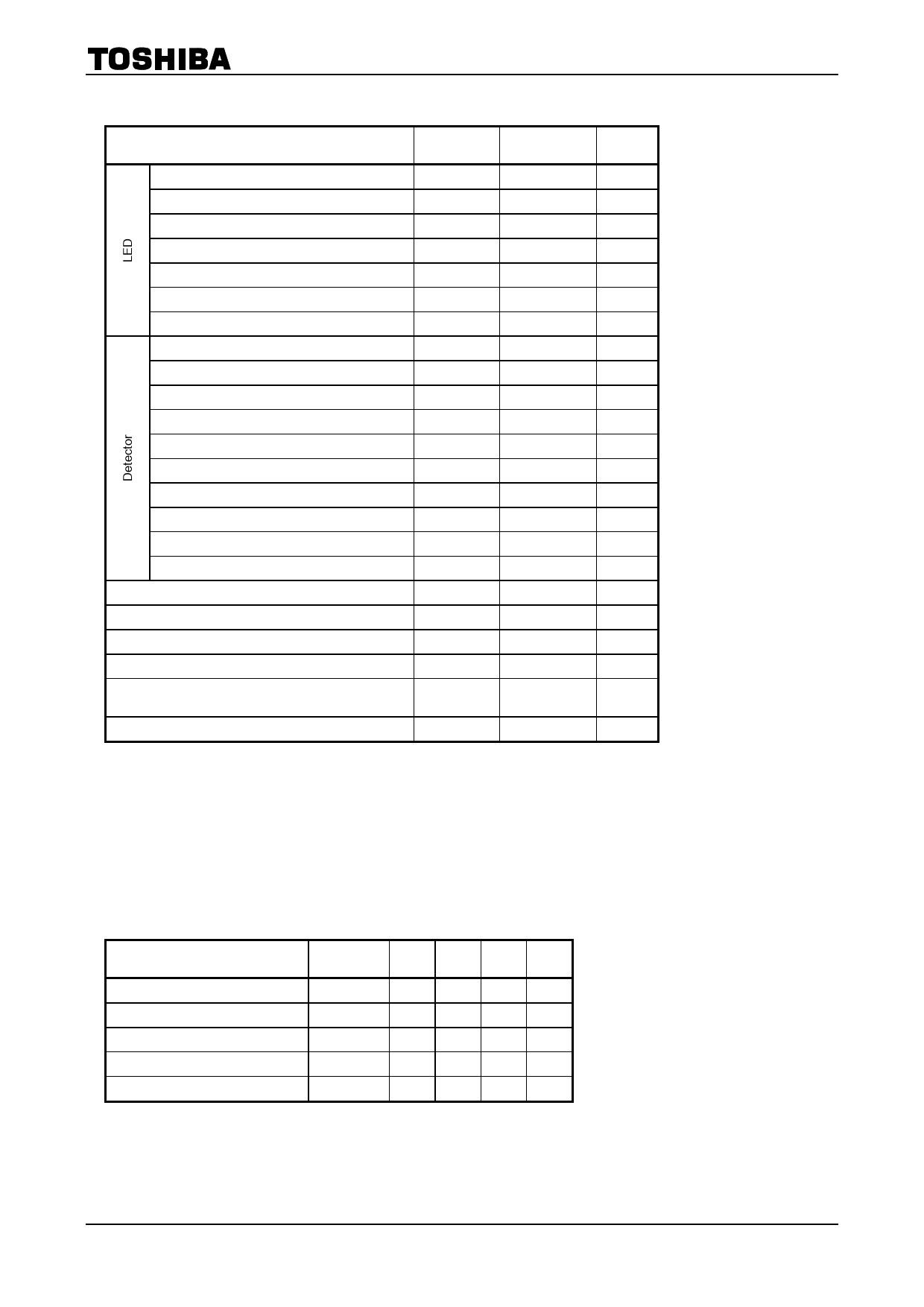
Absolute Maximum Ratings (Ta = 25°C)
Characteristic
Symbol
Rating
Unit
Forward current
Forward current derating (Ta ≥ 39°C)
Peak forward current (100μs pulse, 100pps)
Power dissipation
Power dissipation derating (Ta ≥ 25°C)
Reverse voltage
Junction temperature
Peak forward voltage(RGK = 27kΩ)
Peak reverse voltage(RGK = 27kΩ)
On−state current
On−state current derating (Ta ≥ 25°C)
Peak on−state current (100μs pulse, 120pps)
Peak one cycle surge current
Peak reverse gate voltage
Power dissipation
Power dissipation derating (Ta ≥ 25°C)
Junction temperature
Storage temperature range
Operating temperature range
Lead soldering temperature (10s)
Total package power dissipation
Total package power dissipation derating
(Ta ≥ 25°C)
Isolation voltage (AC, 1 min., R.H. ≤ 60%)
IF
ΔIF / °C
IFP
PD
ΔPD / °C
VR
Tj
VDRM
VRRM
IT(RMS)
ΔIT / °C
ITP
ITSM
VGM
PD
ΔPD / °C
Tj
Tstg
Topr
Tsol
PT
ΔPT / °C
BVS
60
−0.7
1
100
−1.0
5
125
400
400
150
−2.0
3
2
5
150
−2.0
100
−55~125
−55~100
260
250
−3.3
4000
mA
mA / °C
A
mW
mW / °C
V
°C
V
V
mA
mA / °C
A
A
V
mW
mW / °C
°C
°C
°C
°C
mW
mW / °C
Vrms
Note: Using continuously under heavy loads (e.g. the application of high temperature/current/voltage and the
significant change in temperature, etc.) may cause this product to decrease in the reliability significantly even
if the operating conditions (i.e. operating temperature/current/voltage, etc.) are within the absolute maximum
ratings.
Please design the appropriate reliability upon reviewing the Toshiba Semiconductor Reliability Handbook
(“Handling Precautions”/“Derating Concept and Methods”) and individual reliability data (i.e. reliability test
report and estimated failure rate, etc).
Recommended Operating Conditions
Characteristic
Symbol Min. Typ. Max. Unit
Supply voltage
Forward current
Operating temperature
Gate to cathode resistance
Gate to cathode capacity
VAC
IF
Topr
RGK
CGK
―
― 120 Vac
15
20
25 mA
−25 ―
85
°C
―
27
33
kΩ
― 0.01 0.1 μF
Note: Recommended operating conditions are given as a design guideline to obtain expected performance of the
device. Additionally, each item is an independent guideline respectively. In developing designs using this
product, please confirm specified characteristics shown in this document.
2
2007-10-01
Share Link: 