25Q80BVAAG 데이터 시트보기 (PDF) - Winbond
부품명
상세내역
제조사
25Q80BVAAG Datasheet PDF : 75 Pages
| |||
W25Q80BV
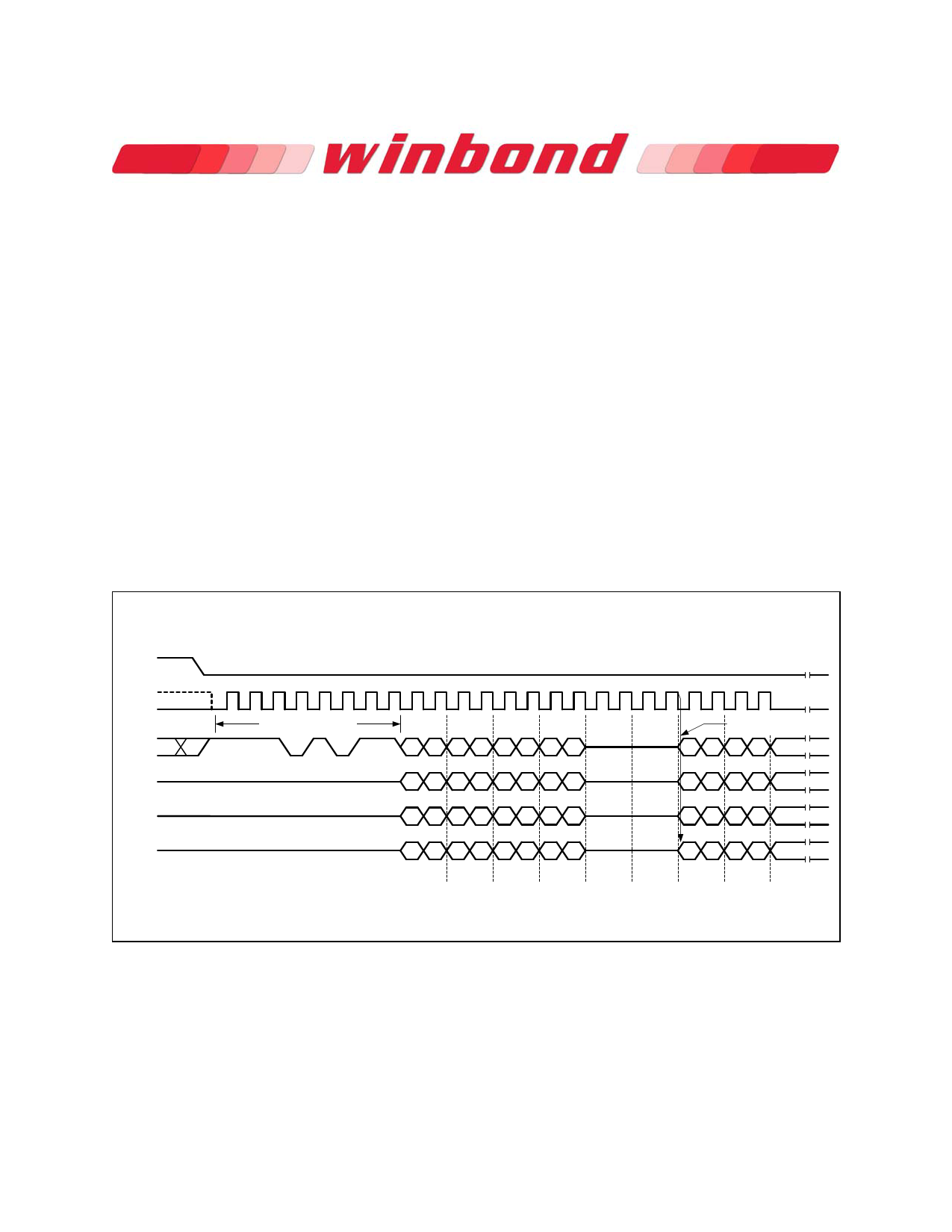
9.2.15 Fast Read Quad I/O (EBh)
The Fast Read Quad I/O (EBh) instruction is similar to the Fast Read Dual I/O (BBh) instruction except
that address and data bits are input and output through four pins IO0, IO1, IO2 and IO3 and four Dummy
clock are required prior to the data output. The Quad I/O dramatically reduces instruction overhead
allowing faster random access for code execution (XIP) directly from the Quad SPI. The Quad Enable bit
(QE) of Status Register-2 must be set to enable the Fast Read Quad I/O Instruction.
Fast Read Quad I/O with “Continuous Read Mode”
The Fast Read Quad I/O instruction can further reduce instruction overhead through setting the
“Continuous Read Mode” bits (M7-0) after the input Address bits (A23-0), as shown in figure 14a. The
upper nibble of the (M7-4) controls the length of the next Fast Read Quad I/O instruction through the
inclusion or exclusion of the first byte instruction code. The lower nibble bits of the (M3-0) are don’t care
(“x”). However, the IO pins should be high-impedance prior to the falling edge of the first data out clock.
If the “Continuous Read Mode” bits M5-4 = (1,0), then the next Fast Read Quad I/O instruction (after /CS
is raised and then lowered) does not require the EBh instruction code, as shown in figure 14b. This
reduces the instruction sequence by eight clocks and allows the Read address to be immediately entered
after /CS is asserted low. If the “Continuous Read Mode” bits M5-4 do not equal to (1,0), the next
instruction (after /CS is raised and then lowered) requires the first byte instruction code, thus returning to
normal operation. A “Continuous Read Mode” Reset instruction can also be used to reset (M7-0) before
issuing normal instructions (See 9.2.20 for detail descriptions).
/CS
CLK
Mode 3
Mode 0
IO0
IO1
IO2
IO3
0 1 2 3 4 5 6 7 8 9 10 11 12 13 14 15 16 17 18 19 20 21 22 23
Instruction (EBh)
A23-16 A15-8
20 16 12 8
A7-0
40
M7-0 Dummy Dummy
40
4
IOs switch from
Input to Output
0404
21 17 13 9 5 1 5 1
51515
22 18 14 10 6 2 6 2
62626
23 19 15 11 7 3 7 3
73
Byte 1
73
Byte 2
7
Byte 3
Figure 14a. Fast Read Quad I/O Instruction Sequence (Initial instruction or previous M5-4 ≠ 10)
- 31 -
Publication Release Date: October 06, 2010
Revision D
Share Link: 