U2402B 데이터 시트보기 (PDF) - Temic Semiconductors
부품명
상세내역
제조사
U2402B Datasheet PDF : 17 Pages
| |||
U2402B
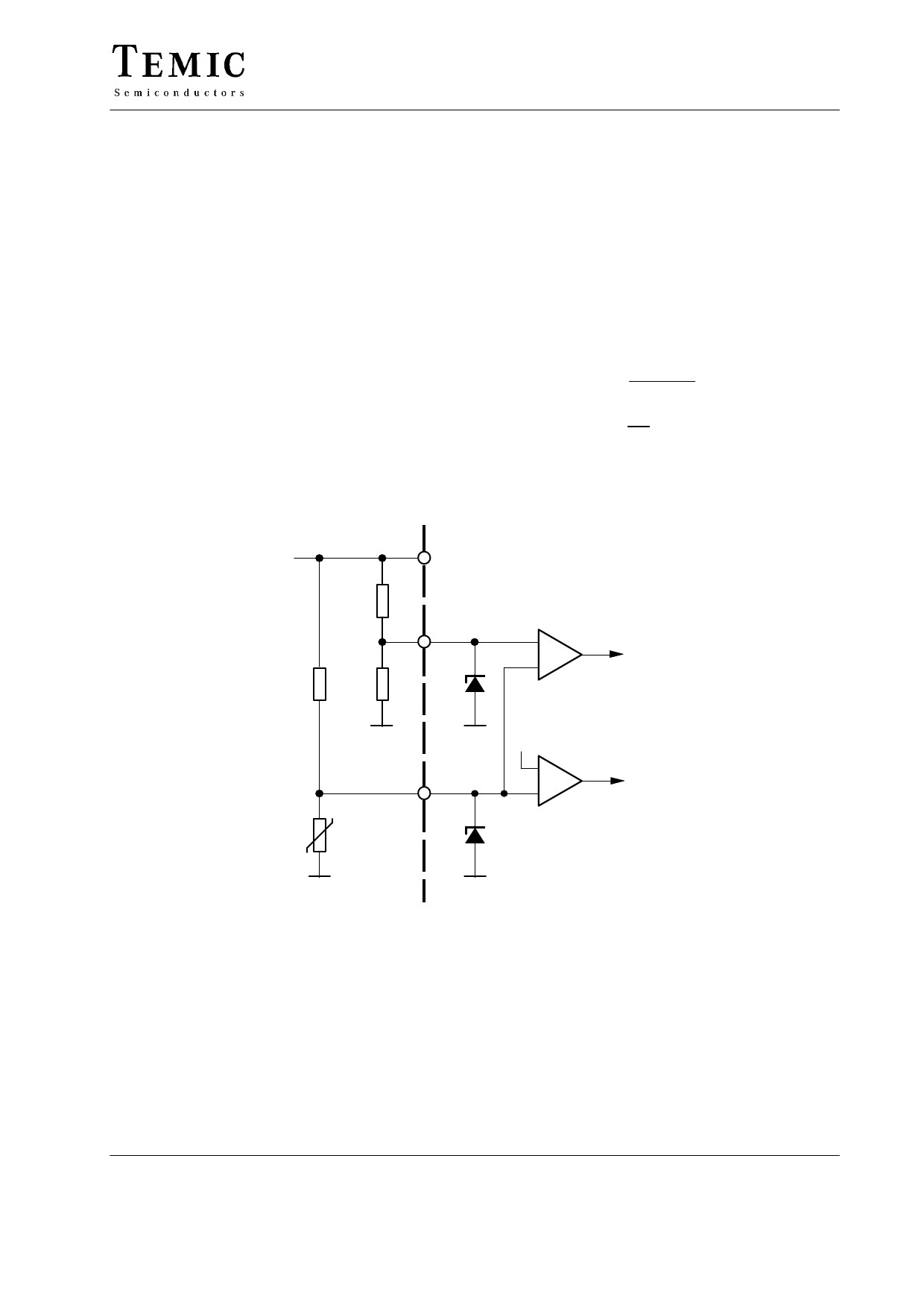
Temperature Control, Figure 7
When the battery temperature is not inside the specified
temperature windows, the overal temperature control will
not allow the charge process. Sensor short circuit or
interruption also leads to switch-off.
Differentiation is made whether the battery exceeds the
maximum allowable temperature, Tmax, during the
charge phase or the battery temperature is outside the
temperature window range before battery connection.
A permanent switch-off follows after a measurement
period of 20.48 s, if the temperature exceeds a specified
level, which is denoted by a status of a red LED1. A charge
sequence will start only when the specified window
temperature range is attained. In such a case, the green
LED2 starts blinking immediately showing a quasi charge
readiness, even though there is no charge current flow.
The temperature window is specified between two
voltage transitions. The upper voltage transition is
specified by the internal reference voltage of 4 V, and the
lower voltage transition is represented by the external
voltage divider resistances RT2 and RT3.
NTC sensors are normally used to control the temperature
of the battery pack. If the resistance values of NTC are
known for maximum and minimum conditions of
allowable temperature, then other resistance values, RT1,
RT2 and RT3 are calculated as follows:
W suppose RT2 = 100 k , then
+ RT1
RNTCmax
VRef – 4V
4V
+ RT3
RNTCmin
RT2
RT1
If NTC sensors are not used, then select the circuit
configuration according to figure 10.
VRef
RT1
NTC
sensor
VRef
14
RT2
Tmax
7
RT3
7V
Sensor
8
7V
+
–
VRef = 4 V
+
–
Figure 7. Temperature window
High
temperature
Low
temperature
94 8682
TELEFUNKEN Semiconductors
Rev. A3, 14-Nov-96
9 (17)
Share Link: 