HMS81016E 데이터 시트보기 (PDF) - Hynix Semiconductor
부품명
상세내역
제조사
HMS81016E Datasheet PDF : 77 Pages
| |||
HMS81004E/08E/16E/24E/32E
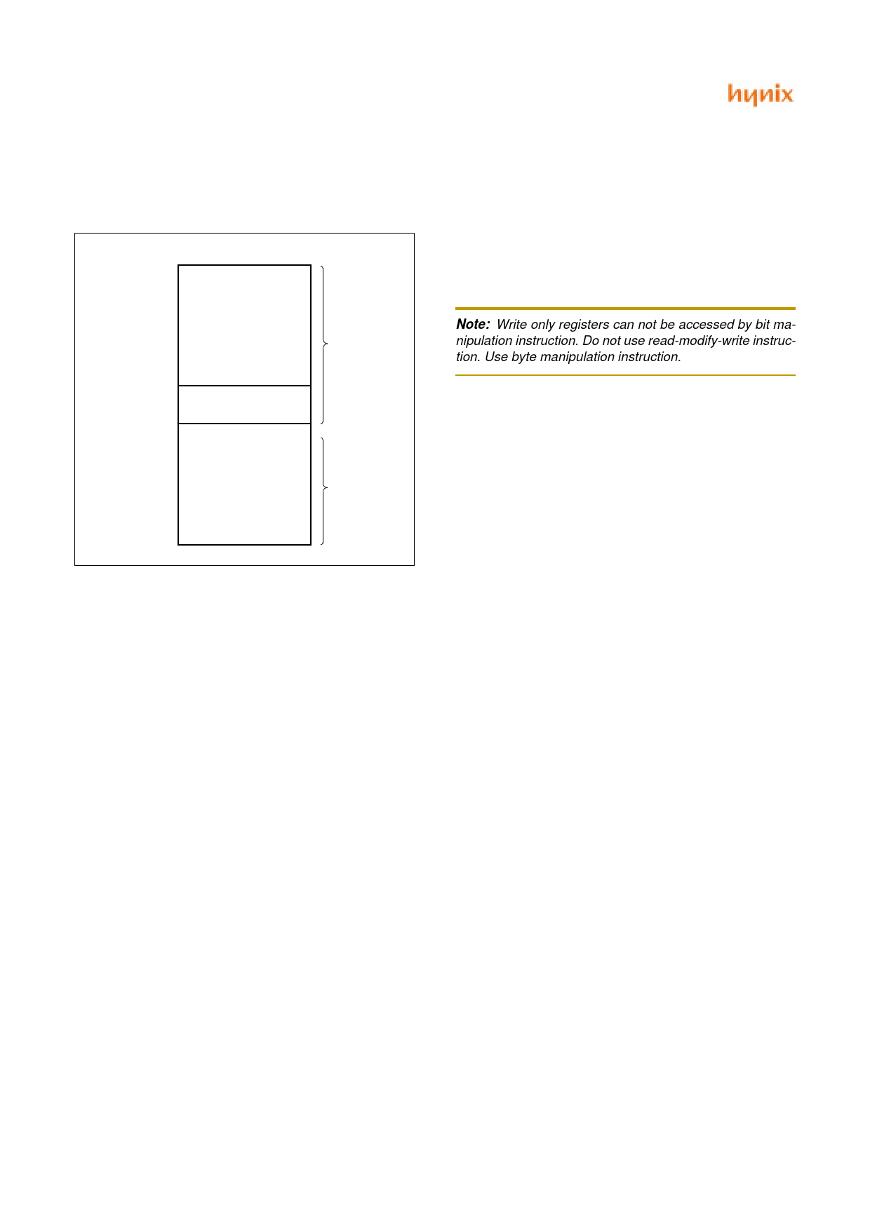
8.3 Data Memory
Figure 8-8 shows the internal Data Memory space availa-
ble. Data Memory is divided into 3 groups, a user RAM,
control registers, Stack.
0000H
00BFH
00C0H
00FFH
0100H
RAM
(192 Bytes)
CONTROL
REGISTERS
RAM (STACK)
(256 Bytes)
PAGE0
PAGE1
01FFH
Figure 8-8 Data Memory Map
User Memory
The HMS81004E/08E/16E/24E/32E has 448 × 8 bits for
the user memory (RAM).
Control Registers
The control registers are used by the CPU and Peripheral
function blocks for controlling the desired operation of the
device. Therefore these registers contain control and status
bits for the interrupt system, the timer/ counters, analog to
digital converters and I/O ports. The control registers are in
address range of 0C0H to 0FFH.
Note that unoccupied addresses may not be implemented
on the chip. Read accesses to these addresses will in gen-
eral return random data, and write accesses will have an in-
determinate effect.
More detailed informations of each register are explained
in each peripheral section.
Note: Write only registers can not be accessed by bit ma-
nipulation instruction. Do not use read-modify-write instruc-
tion. Use byte manipulation instruction.
Example; To write at CKCTLR
LDM CLCTLR,#09H ;Divide ratio ÷16
Stack Area
The stack provides the area where the return address is
saved before a jump is performed during the processing
routine at the execution of a subroutine call instruction or
the acceptance of an interrupt.
When returning from the processing routine, executing the
subroutine return instruction [RET] restores the contents of
the program counter from the stack; executing the interrupt
return instruction [RETI] restores the contents of the pro-
gram counter and flags.
The save/restore locations in the stack are determined by
the stack pointed (SP). The SP is automatically decreased
after the saving, and increased before the restoring. This
means the value of the SP indicates the stack location
number for the next save. Refer to Figure 8-3 on page 17.
22
JUNE 2001 Ver 1.00
Share Link: 