NE555 데이터 시트보기 (PDF) - STMicroelectronics
부품명
상세내역
제조사
NE555 Datasheet PDF : 20 Pages
| |||
NE555 - SA555 - SE555
Application information
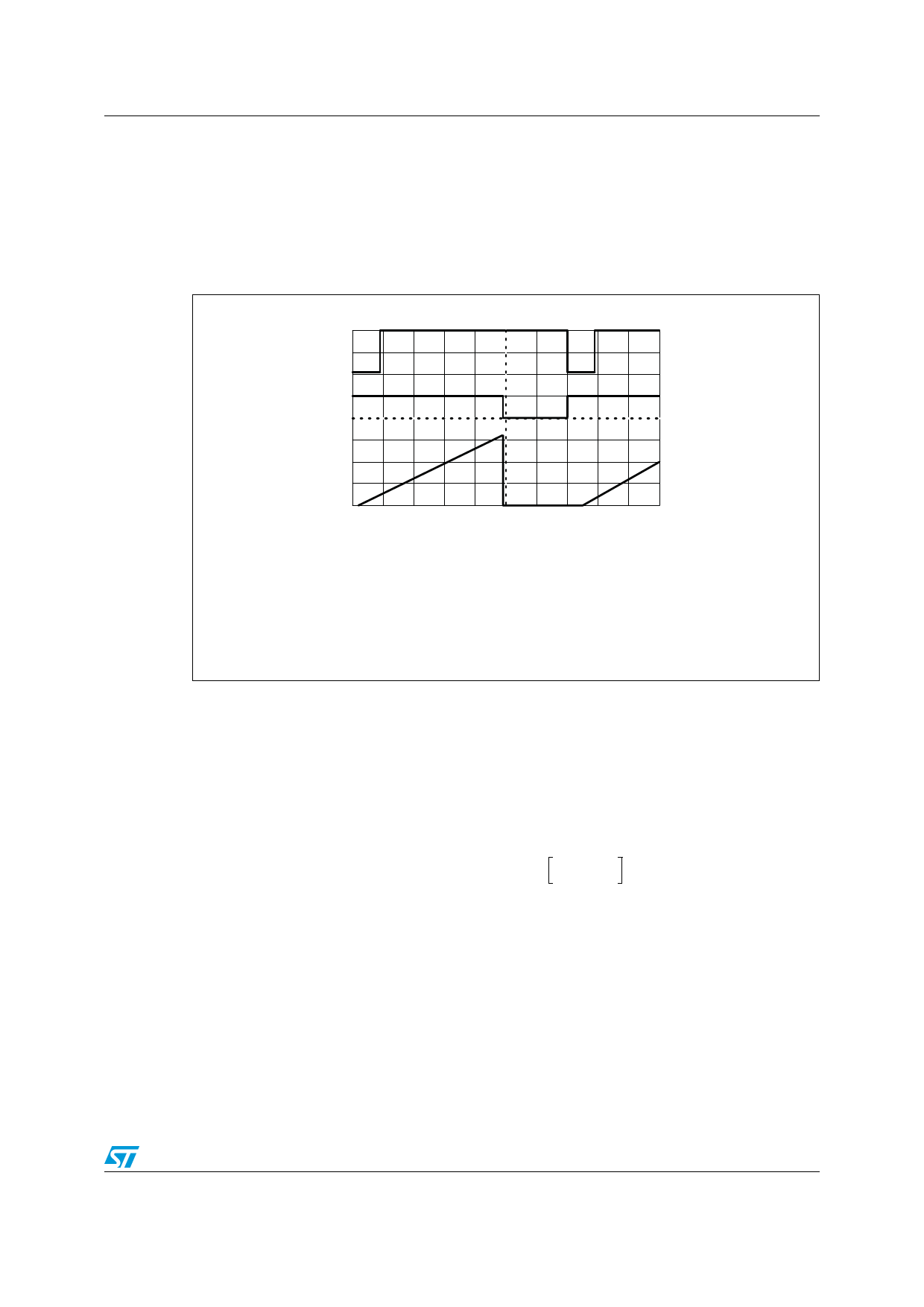
Figure 20 shows the waveforms generator by the linear ramp.
The time interval is given by:
T = --R(--2---1-/-3---V--V--c--c-c--c------R-V---E-B----E-(--R---(-1-R---+-1--R-+---2-R---)-2--C-)-- VBE = 0.6V
Figure 20. Linear ramp
VCC = 5 V
Time:
20 µs/DIV
R1 + 47 kΩ
R2 = 100 kΩ
RE = 2.7 kΩ
C = 0.01 µF
Top trace: input 3 V/DIV
Middle trace: output 5 V/DIV
Bottom trace: output 5 V/DIV
Bottom trace: capacitor voltage 1 V/DIV
4.5
50% duty cycle oscillator
For a 50% duty cycle, the resistors RA and RB can be connected as in Figure 21. The time
period for the output high is the same as for astable operation (see Section 4.2 on page 9):
t1 = 0.693 RA C
For the output low it is
t2= [(R. RB)/(RA+RB)].C.Ln
R-----B------–----2----R-----A--
2RB – RA
Thus the frequency of oscillation is:
f = -------1---------
t1 + t2
Doc ID 2182 Rev 6
13/20
Share Link: 