PC812 데이터 시트보기 (PDF) - Sharp Electronics
부품명
상세내역
제조사
PC812 Datasheet PDF : 4 Pages
| |||
PC812
s Electro-optical Characteristics
(Ta = 25˚C)
Input
Output
Transfer
charac-
teristics
Parameter
Symbol
Conditions
MIN.
Forward voltage
V F IF = 20mA
-
Peak forward voltage
V FM IFM = 0.5A
-
Reverse current
IR VR = 4V
-
Terminal capacitance
Ct V = 0, f = 1kHz
-
Collector dark current
ICEO V CE = 20V, IF = 0
-
*4 Current transfer ratio
C T R IF = 5 m A , VCE = 5V
90
Collector-emitter saturation voltage V CE (sat) IF = 20mA, IC = 1mA
-
Isolation resistance
RISO DC500V, 40 to 60% RH
5 x 10¹⁰
Floating capacitance
Cf V = 0, f = 1MHz
-
Cut-off frequency
fc VCE = 5V, IC = 2mA, RL = 100 Ω, - 3dB
15
*4 Response time
Rise time
tr
VCE = 2V, IC = 2mA, RL = 100 Ω
-
Fall time
tf
-
*5 Common mode rejection voltage
V CM dV/dt = 2kV/ µ s, RL= 470 Ω, Vnp = 100mV, IF = 0 -
TYP.
1.2
-
-
30
-
-
0.1
1011
0.6
80
4
5
1.5
MAX.
1.4
3.0
10
200
10 - 7
480
0.2
-
1.0
-
18
20
-
Unit
V
V
µA
pF
A
%
V
Ω
pF
kHz
µs
µs
kV
*4 Classification table of current transfer ratio is shown below.
Model
No.
Rank CTR ( % ) tr( µ s)
tf( µ s)
mark
TYP. MAX. TYP. MAX.
PC812A A
90 to 180 3 14 4 16
PC812B B 150 to 180 4 16 5 18
PC812C C 240 to 480 5 18 7 20
PC812 A , B o r C 90 to 480 4 18 5 20
Measurement
conditions
I = 5mA
VCE = 5V
Ta = 25˚C
V CE = 2V
IC= 2mA
RL = 100 Ω
Ta = 25˚C
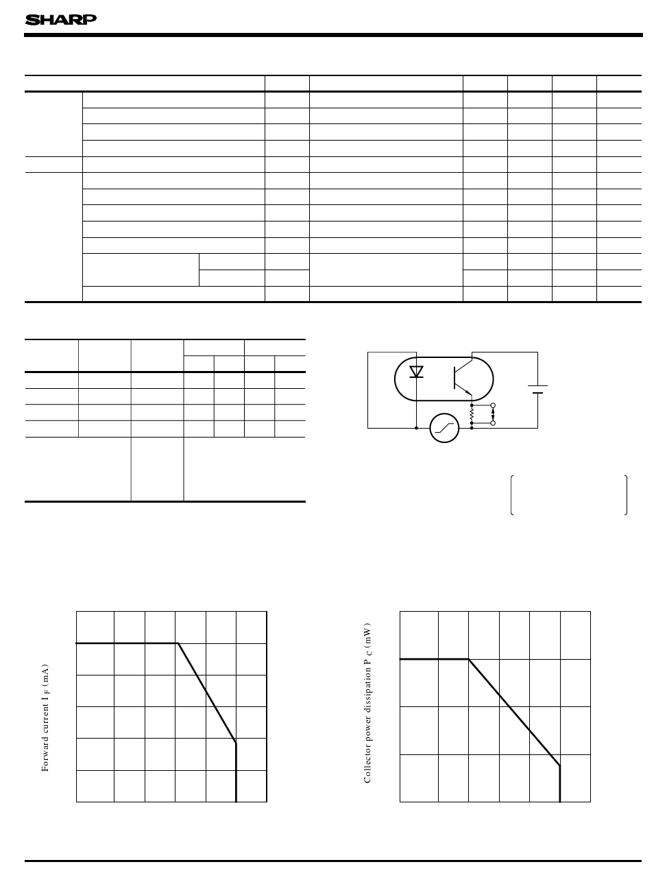
*5 Test Circuit for VCM
RL Vnp
VCC = 9V
VCM
VCM : Common mode rejection
voltage
(higher value of pulse wave)
dV/dt : Rising factor of voltage
Test condition
Vnp = 100mV, RL = 470 Ω
dV/dt = 2kV/ µ s, IF = 0
Fig. 1 Forward Current vs.
Ambient Temperature
60
50
40
30
20
10
0
- 30
0 25 50 75 100 125
Ambient temperature T a (˚C)
Fig. 2 Collector Power Dissipation vs.
Ambient Temperature
200
150
100
50
0
- 30
0 25 50 75 100 125
Ambient temperature T a (˚C)
Share Link: 