MAX2121 데이터 시트보기 (PDF) - Maxim Integrated
부품명
상세내역
제조사
MAX2121 Datasheet PDF : 18 Pages
| |||
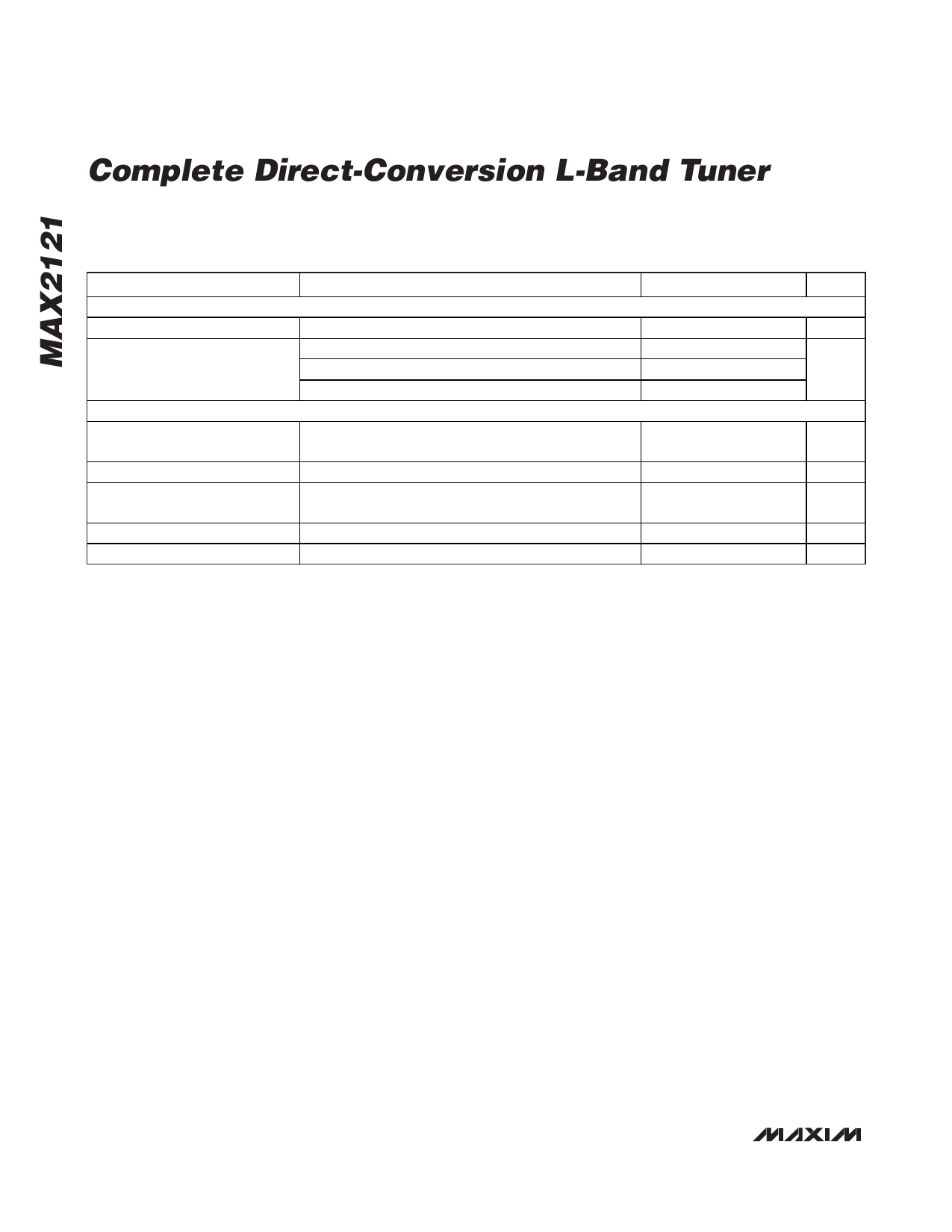
Complete Direct-Conversion L-Band Tuner
AC ELECTRICAL CHARACTERISTICS (continued)
(MAX2121 Evaluation Kit: VCC = +3.13V to +3.47V, TA = -40°C to +85°C, default register settings except BBG[3:0] = 1111. Typical
values measured at VCC = +3.3V, TA = +25°C, unless otherwise noted.) (Note 1)
PARAMETER
CONDITIONS
MIN TYP MAX UNITS
VOLTAGE-CONTROLLED OSCILLATOR AND LO GENERATION
Guaranteed LO Frequency Range
925
2175 MHz
fOFFSET = 10kHz
LO Phase Noise
fOFFSET = 100kHz
fOFFSET = 1MHz
XTAL/REFERENCE OSCILLATOR INPUT AND OUTPUT BUFFER
-97
-100
-122
dBc/H z
XTAL Oscillator Frequency
Range fXTAL
Parallel-resonance-mode crystal (Note 7)
12
30
MHz
Input Overdrive Level
AC-coupled sine-wave input
0.5
1
2.0
VP-P
XTAL Output-Buffer Divider
Range
1
8
XTAL Output Voltage Swing
XTAL Output Duty Cycle
12MHz to 30MHz, CLOAD = 10pF
1
1.5
2
VP-P
50
%
Note 1: Min/max values are production tested at TA = +25°C. Min/max limits at TA = -40°C and TA = +85°C are guaranteed by
design and characterization.
Note 2: Guaranteed by design and characterization at TA = +25°C.
Note 3: Input gain range specifications met over this band.
Note 4: In-band IIP3 test conditions: GC1 set to provide the nominal baseband output drive when mixing down a -23dBm tone at
2175MHz to 5MHz baseband (fLO = 2170MHz). Baseband gain is set to its default value (BBG[3:0] = 1011). Two tones at
-26dBm each are applied at 1919MHz and 1663MHz. The IM3 tone at 3MHz is measured at baseband, but is referred to the
RF input.
Note 5: Out-of-band IIP3 test conditions: GC1 set to provide nominal baseband output drive when mixing down a -23dBm tone at
2175MHz to 5MHz baseband (fLO = 2170MHz). Baseband gain is set to its default value (BBG[3:0] = 1011). Two tones at
-20dBm each are applied at 1919MHz and 1663MHz. The IM3 tone at 5MHz is measured at baseband, but is referred to the
RF input.
Note 6: Input IP2 test conditions: GC1 set to provide nominal baseband output drive when mixing down a -23dBm tone at 2175MHz
to 5MHz baseband (fLO = 2170MHz). Baseband gain is set to its default value (BBG[3:0] = 1011). Two tones at -20dBm
each are applied at 925MHz and 1250MHz. The IM2 tone at 5MHz is measured at baseband, but is referred to the RF input.
Note 7: See Table 16 for crystal ESR requirements.
4 _______________________________________________________________________________________
Share Link: 