13NM60N(2011) 데이터 시트보기 (PDF) - STMicroelectronics
부품명
상세내역
제조사
13NM60N
(Rev.:2011)
(Rev.:2011)
STMicroelectronics

13NM60N Datasheet PDF : 14 Pages
| |||
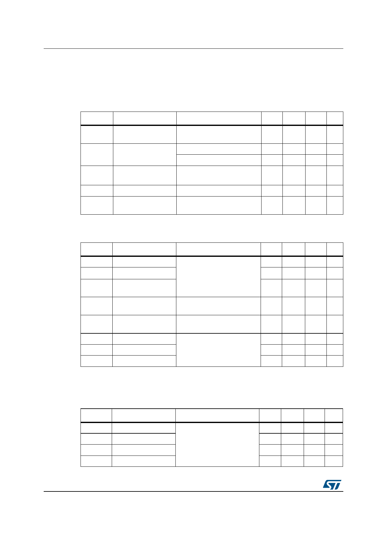
Electrical characteristics
2
Electrical characteristics
STL13NM60N
(TC = 25 °C unless otherwise specified)
Table 4. On /off states
Symbol
Parameter
Test conditions
V(BR)DSS
Drain-source
breakdown voltage
ID = 1 mA, VGS = 0
IDSS
IGSS
VGS(th)
RDS(on)
Zero gate voltage
VDS = Max rating
drain current (VGS = 0) VDS = Max rating, TC=125 °C
Gate-body leakage
current (VDS = 0)
VGS = ± 25 V
Gate threshold voltage VDS = VGS, ID = 250 µA
Static drain-source on
resistance
VGS = 10 V, ID = 5 A
Min. Typ. Max. Unit
600
V
1 µA
100 µA
100 nA
2
3
4
V
0.320 0.385 Ω
Table 5. Dynamic
Symbol
Parameter
Test conditions
Min. Typ. Max. Unit
Ciss
Coss
Crss
Input capacitance
Output capacitance
Reverse transfer
capacitance
VDS = 50 V, f = 1 MHz,
VGS = 0
790
pF
-
60
- pF
3.6
pF
Coss
(1)
eq.
Output equivalent
capacitance
VDS = 0 to 480 V, VGS = 0
-
135
- pF
RG
Intrinsic gate
resistance
f = 1 MHz open drain
-
4.7
-
Ω
Qg
Total gate charge
VDD = 480 V, ID = 10 A,
Qgs Gate-source charge VGS = 10 V
Qgd Gate-drain charge
(see Figure 14)
30
nC
-
4
- nC
15
nC
1. Coss eq. is defined as a constant equivalent capacitance giving the same charging time as Coss when VDS
increases from 0 to 80% VDS.
Table 6. Switching times
Symbol
Parameter
td(on)
tr
td(off)
tf
Turn-on delay time
Rise time
Turn-off delay time
Fall time
Test conditions
VDD = 300 V, ID = 10 A,
RG = 4.7 Ω, VGS = 10 V
(see Figure 18)
Min.
-
Typ.
13
25
85
50
Max Unit
ns
ns
-
ns
ns
4/14
Doc ID 018870 Rev 1
Share Link: