TTSI1K16T3TL 데이터 시트보기 (PDF) - Agere -> LSI Corporation
부품명
상세내역
제조사
TTSI1K16T3TL Datasheet PDF : 64 Pages
| |||
TTSI1K16T
1024-Channel, 16-Highway Time-Slot Interchanger
Preliminary Data Sheet
February 1999
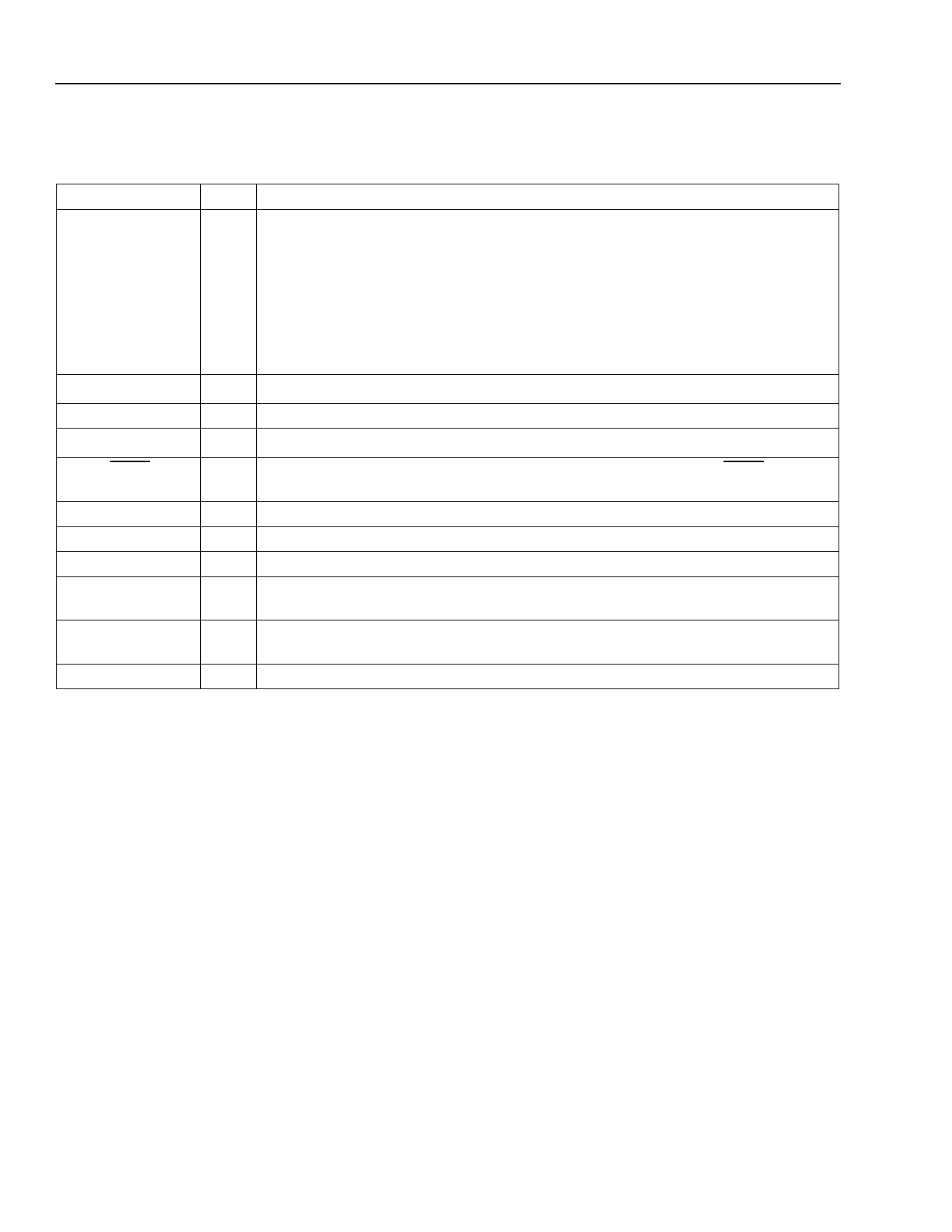
Pin Information (continued)
Table 4. TTSI1K16T Pin Descriptions (continued)
Symbol
Type*
Description
TXOE[0—15]
O Transmit Output Enables 0—15. These output pins reflect the active/high-imped-
ance status for the corresponding transmit highways. They are continuously driven
to reflect the status of the output enables of the transmit highways, regardless of
whether or not external driver mode is enabled via the ED (bit 6) in the general com-
mand register. The external driver for transmit highway [i] should be enabled when
TXOE[i] is a 1.
Also see Table 41, Transmit Highway 3-State Options, on page 49 for other meth-
ods of 3-stating the transmit highways.
TDI
TCK
Iu JTAG Test Data Input.
I JTAG Test Clock. Maximum 10 MHz.
TMS
Iu JTAG Test Mode Select.
TRST
Id JTAG Test Reset (Active-Low). To disable the JTAG interface, tie TRST low or
leave unconnected.
TDO
O Test Data Output.
VDD
P 3.3 V Supply. All VDD leads must be connected to the 3.3 V supply.
VSS
P Ground.
VDDPLL
P 3.3 V PLL Supply. VSSPLL and VDDPLL should be decoupled with a high-speed
capacitor with a value in the range of 2 µF—5 µF.
VSSPLL
P PLL Ground. VSSPLL and VDDPLL should be decoupled with a high-speed capaci-
tor with a value in the range of 2 µF—5 µF.
NC
— No Connect. This pin must be left unconnected.
*Iu indicates internal 100 kΩ pull-up resistor, and Id indicates internal 17.5 kΩ pull-down resistor.
12
Lucent Technologies Inc.
Share Link: 