TFA9843J 데이터 시트보기 (PDF) - NXP Semiconductors.
부품명
상세내역
제조사
TFA9843J Datasheet PDF : 21 Pages
| |||
Philips Semiconductors
TFA9843J
2-channel audio amplifier (2 x SE or 1 x BTL)
At VCC = 18 V and RL = 4 Ω (2 × SE) the measured worst-case sine-wave dissipation
is 8.4 W; see Figure 13. For Tj(max) = 150 °C the temperature raise, caused by the
power dissipation, is: 150 − 60 = 90 °C:
P × Rth(tot) = 90 °C
Rth(tot) = 90/8.4 = 10.7 K/W
Rth(h-a) = Rth(tot) − Rth(j-mb) = 10.7 − 2.0 = 8.7 K/W
This calculation is for an application at worst-case (stereo) sine-wave output signals.
In practice music signals will be applied, which decreases the maximum power
dissipation to approximately half of the sine-wave power dissipation (see
Section 8.2.2). This allows for the use of a smaller heatsink:
P × Rth(tot) = 90 °C
Rth(tot) = 90/4.2 = 21.4 K/W
Rth(h-a) = Rth(tot) − Rth(j-mb) = 21.4 − 2.0 = 19.4 K/W
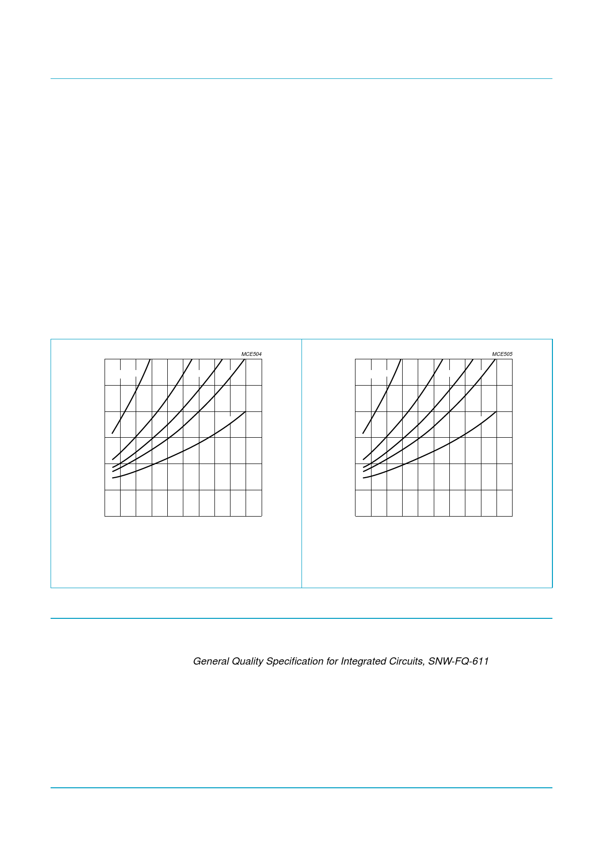
150
Tj
(˚C)
RL = 2 Ω
100
MCE504
4Ω 6Ω 8Ω
16 Ω
150
Tj
(˚C)
RL = 1 Ω
100
MCE505
2Ω 3Ω 4Ω
8Ω
50
50
0
8
12
16
20
24
28
VCC (V)
2 × SE loads; Tamb = 25 °C; external heatsink of 10 K/W;
music signals.
Fig 22. Junction temperature versus supply voltage.
14. Test information
0
8
12
16
20
24
28
VCC (V)
BTL loads; Tamb = 25 °C; external heatsink of 10 K/W;
music signals.
Fig 23. Junction temperature versus supply voltage.
14.1 Quality information
The General Quality Specification for Integrated Circuits, SNW-FQ-611 is applicable.
9397 750 12587
Preliminary data
Rev. 02 — 19 January 2004
© Koninklijke Philips Electronics N.V. 2004. All rights reserved.
16 of 21
Share Link: 