74LCX04TTR 데이터 시트보기 (PDF) - STMicroelectronics
부품명
상세내역
제조사
74LCX04TTR Datasheet PDF : 8 Pages
| |||
74LCX04
AC ELECTRICAL CHARACTERISTICS
Test Condition
Value
Symbol
Parameter
VCC
CL RL ts = tr -40 to 85 °C
-55 to 125 °C Unit
(V)
(pF) (Ω) (ns) Min. Max. Min. Max.
tPLH tPHL Propagation Delay
Time
2.7
3.0 to 3.6
50 500 2.5
1.0
6.0
5.2
6.9
ns
6.0
tOSLH Output To Output
3.0 to 3.6 50 500 2.5
1.0
tOSHL Skew Time (note1,
2)
1.0
ns
1) Skew is defined as the absolute value of the difference between the actual propagation delay for any two outputs of the same device switch-
ing in the same direction, either HIGH or LOW (tOSLH = | tPLHm - tPLHn|, tOSHL = | tPHLm - tPHLn|)
2) Parameter guaranteed by design
CAPACITIVE CHARACTERISTICS
Test Condition
Value
Symbol
Parameter
VCC
(V)
TA = 25 °C
Unit
Min. Typ. Max.
CIN
Input Capacitance
3.3
VIN = 0 to VCC
5
pF
CPD Power Dissipation Capacitance
3.3
(note 1)
fIN = 10MHz
VIN = 0 or VCC
41
pF
1) CPD is defined as the value of the IC’s internal equivalent capacitance which is calculated from the operating current consumption without
load. (Refer to Test Circuit). Average operating current can be obtained by the following equation. ICC(opr) = CPD x VCC x fIN + ICC/6 (per gate)
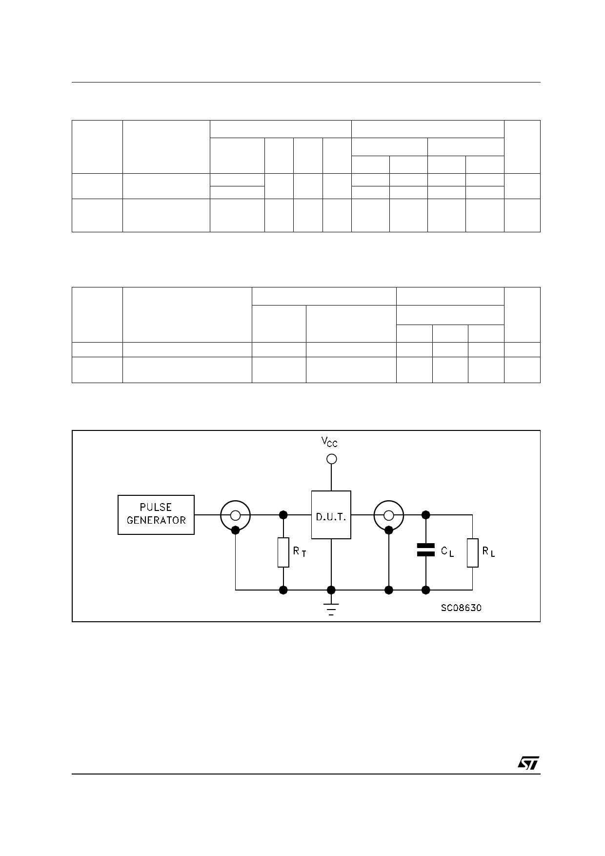
TEST CIRCUIT
CL = 50 pF or equivalent (includes jig and probe capacitance)
RL = 500Ω or equivalent
RT = ZOUT of pulse generator (typically 50Ω)
4/8
Share Link: 