AAT3682 데이터 시트보기 (PDF) - Skyworks Solutions
부품명
상세내역
제조사
AAT3682 Datasheet PDF : 18 Pages
| |||
VF = Diode forward voltage
ICC = Constant current charge level for the system
Schottky Diodes
Schottky diodes are selected for this application because
they have a low forward voltage drop, typically between
0.3V and 0.4V. A lower VF permits a lower voltage drop
at the constant current charge level set by the system;
less power will be dissipated in this element of the cir-
cuit. A Schottky diode allows for lower power dissipation,
smaller component package sizes, and greater circuit
layout densities.
DATA SHEET
AAT3682
Li-Ion/Polymer Linear Battery Charger
Rectifier Diodes
Any general purpose rectifier diode can be used with the
AAT3682 application circuit in place of a higher cost
Schottky diode. The design trade-off is that a rectifier
diode has a high forward voltage drop. VF for a typical
silicon rectifier diode is in the range of 0.7V. A higher VF
will place an input supply voltage requirement for the
battery charger system. This will also require a higher
power rated diode since the voltage drop at the constant
current charge amplitude will be greater. Refer to the
previously stated equations to calculate the minimum VIN
and diode PD for a given application.
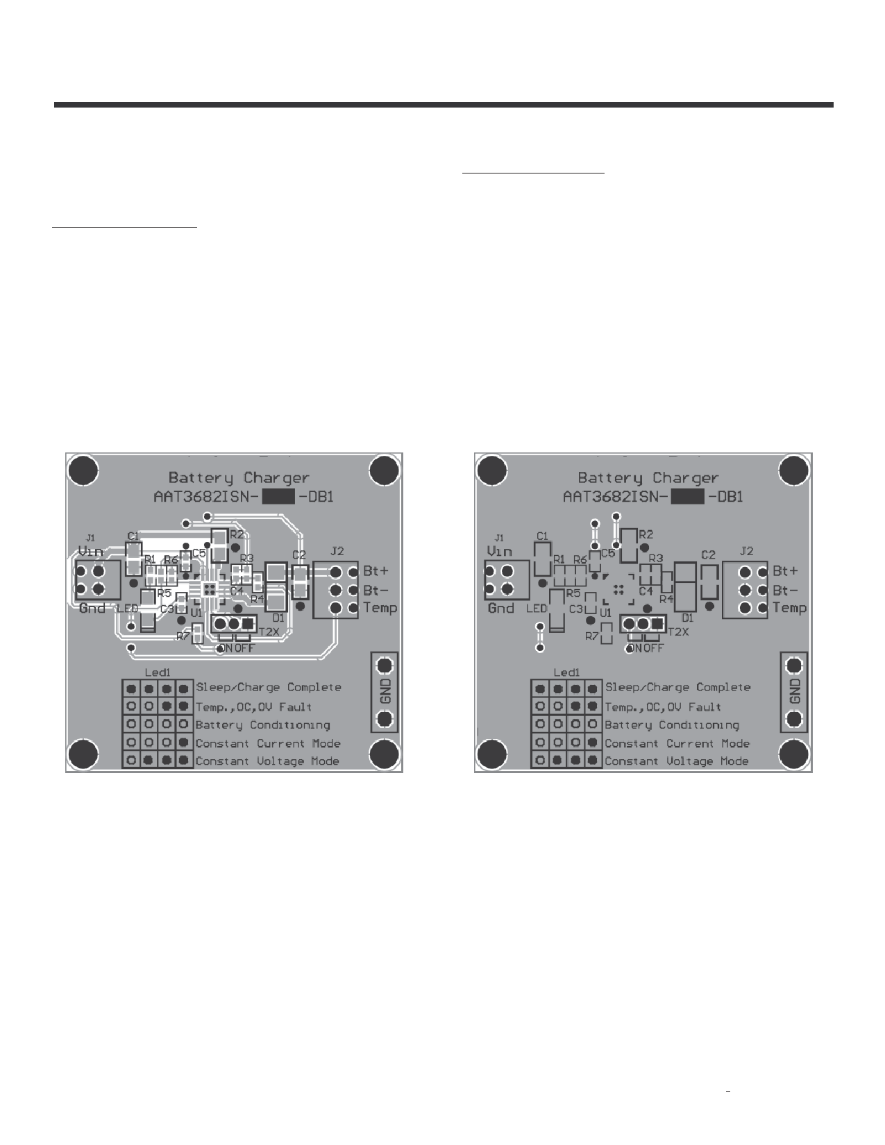
Figure 6: Evaluation Board Top Side Layout.
Figure 7: Evaluation Board Bottom Side Layout.
Skyworks Solutions, Inc. • Phone [781] 376-3000 • Fax [781] 376-3100 • sales@skyworksinc.com • www.skyworksinc.com
16
201884B • Skyworks Proprietary Information • Products and Product Information are Subject to Change Without Notice. • April 25, 2012
Share Link: 