MAX4800ACQI 데이터 시트보기 (PDF) - Maxim Integrated
부품명
상세내역
제조사
MAX4800ACQI
Maxim Integrated

MAX4800ACQI Datasheet PDF : 16 Pages
| |||
MAX4800A/MAX4802A
Low-Charge-Injection, 8-Channel, High-Voltage
Analog Switches with 20MHz Serial Interface
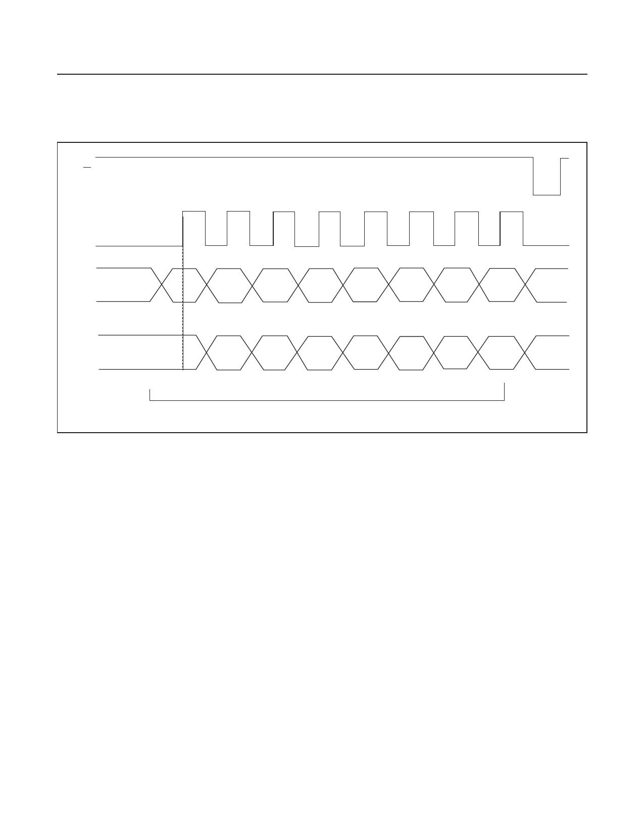
LE
CLK
DIN
DOUT
D7
D6
D5
D4
D3
D2
D1
D0
MSB
LSB
D7
D6
D5
D4
D3
D2
D1
D0
D7
DATA FROM PREVIOUS DATA BYTE POWER-UP DEFAULT: D7–D0 = 0
Figure 2. Latch-Enable Interface Timing
The VPP and VNN high-voltage supplies are not required
to be symmetrical, but the voltage difference VPP - VNN
must not exceed 200V.
Bleed Resistors (MAX4802A)
The MAX4802A features integrated 35kΩ bleed resis-
tors to discharge capacitive loads such as piezoelectric
transducers. Each analog-switch terminal is connected to
RGND with a bleed resistor.
Serial Interface
The devices are controlled by a serial interface with an
8-bit serial shift register and transparent latch. Each of
the eight data bits controls a single analog switch (see
Table 1). Data on DIN is clocked with the most significant
bit (MSB) first into the shift register on the rising edge of
CLK. Data is clocked out of the shift register onto DOUT
on the rising edge of CLK. DOUT reflects the status of
DIN, delayed by eight clock cycles (see Figures 1 and 2).
Latch Enable (LE)
Drive LE logic-low to change the contents of the latch and
update the state of the high-voltage switches (Figure 2).
Drive LE logic-high to freeze the contents of the latch and
prevent changes to the switch states. To reduce noise
due to clock feedthrough, drive LE logic-high while data is
clocked into the shift register. After the data shift register
is loaded with valid data, pulse LE logic-low to load the
contents of the shift register into the latch.
Latch Clear (CLR)
The devices feature a latch clear input. Drive CLR
logic-high to reset the contents of the latch to zero and
open all switches. CLR does not affect the contents of
the data shift register. Pulse LE logic-low to reload the
contents of the shift register into the latch.
Power-On Reset
The devices feature a power-on reset circuit to ensure all
switches are open at power-on. The internal 8-bit serial
shift register and latch are set to zero on power-up.
www.maximintegrated.com
Maxim Integrated │ 11
Share Link: