EL4442C 데이터 시트보기 (PDF) - Elantec -> Intersil
부품명
상세내역
제조사
EL4442C Datasheet PDF : 16 Pages
| |||
EL4421C 22C 41C 42C 43C 44C
Multiplexed-Input Video Amplifiers
Applications Information Contd
Capacitive loads will cause peaking in the fre-
quency response If capacitive loads must be driv-
en a small-valued series resistor can be used to
isolate it 12X to 51X should suffice A 22X series
resistor will limit peaking to 2 5 dB with even a
220 pF load
Input Connections
The input transistors can be driven from resistive
and capacitive sources but are capable of oscilla-
tion when presented with an inductive input It
takes about 80 nH of series inductance to make
the inputs actually oscillate equivalent to four
inches of unshielded wiring or about 6 of unter-
minated input transmission line The oscillation
has a characteristic frequency of 500 MHz
Often simply placing one’s finger (via a metal
probe) or an oscilloscope probe on the input will
kill the oscillation Normal high-frequency con-
struction obviates any such problems where the
input source is reasonably close to the mux-amp
input If this is not possible one can insert series
resistors of around 51X to de-Q the inputs
Feedback Connections
A feedback divider is used to increase circuit
gain and some precautions should be observed
The first is that parasitic capacitance at the in-
put will add phase lag to the feedback path and
increase frequency response peaking or even
cause oscillation One solution is to choose feed-
back resistors whose parallel value is low The
pole frequency of the feedback network should be
maintained above at least 200 MHz For a 3 pF
parasitic this requires that the feedback divider
have less than 265X impedance equivalent to
two 510X resistors when a gain of a2 is desired
Alternatively a small capacitor across RF can be
used to create more of a frequency-compensated
divider The value of the capacitor should match
the parasitic capacitance at the input It is also
practical to place small capacitors across both the
feedback resistors (whose values maintain the de-
sired gain) to swamp out parasitics For instance
two 10 pF capacitors across equal divider resis-
tors will dominate parasitic effects and allow a
higher divider resistance
The other major concern about the divider con-
cerns unselected-channel crosstalk The differen-
tial input impedance of each input stage is
around 200 KX The unselected input’s signal
sources thus drive current through that input im-
pedance into the feedback divider inducing an
unwanted output The gain from unselected in-
put to output the crosstalk attenuation if RF
RIN In unity-gain connection the feedback resis-
tor is 0X and very little crosstalk is induced For
a gain of a2 the crosstalk is about 60 dB
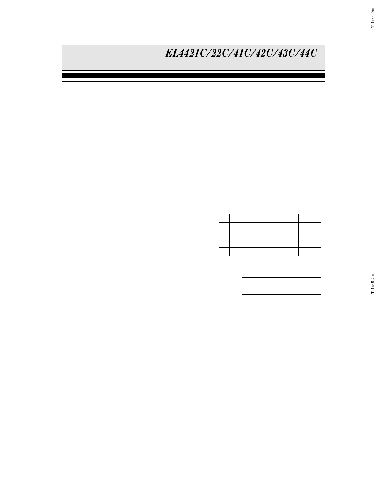
Feedthrough Attenuation
The channels have different crosstalk levels with
different inputs Here is the typical attenuation
for all combinations of inputs for the mux-amps
at 3 58 MHz
Feedthrough of EL4441 and EL4443 at 3 58 MHz
In1
In2
In3
In4
Select
Inputs
A1A0
00 Selected b77 dB b90 dB b92 dB
01 b80 dB Selected b77 dB b90 dB
10 b101 dB b76 dB Selected b66 dB
11 b96 dB b84 dB b66 dB Selected
Feedthrough of EL4421 at 3 58 MHz
In1
In2
Channel Select
0
Selected
b88 dB
Input A0
1
b93 dB
Selected
Switching Glitches
The output of the mux-amps produces a small
‘‘glitch’’ voltage in response to a logic input
change A peak amplitude of only about 90 mV
occurs and the transient settles out in 20 ns The
glitch does not change amplitude with different
gain settings
With the four-input multiplexers when two logic
inputs are simultaneously changed the glitch
amplitude doubles The increase can be a avoided
by keeping transitions at least 6 ns apart This
can be accomplished by inserting one gate delay
in one of the two logic inputs when they are truly
synchronous
13
Share Link: 