MC74F377DW 데이터 시트보기 (PDF) - Motorola => Freescale
부품명
상세내역
제조사
MC74F377DW Datasheet PDF : 3 Pages
| |||
MC74F377
FUNCTIONAL DESCRIPTION
The MC74F377 has eight edge-triggered D-type flip-flops
with individual D inputs and Q outputs. The common buffered
Clock (CP) input loads all flip-flops simultaneously, when the
Enable (E) is LOW.
The register is fully edge-triggered. The state of each D in-
put, one setup time before the LOW-to-HIGH clock transition,
is transferred to the corresponding flip-flop’s Q output.
The E input must be stable one setup time prior to the LOW-
to-HIGH clock transition for predictable operation.
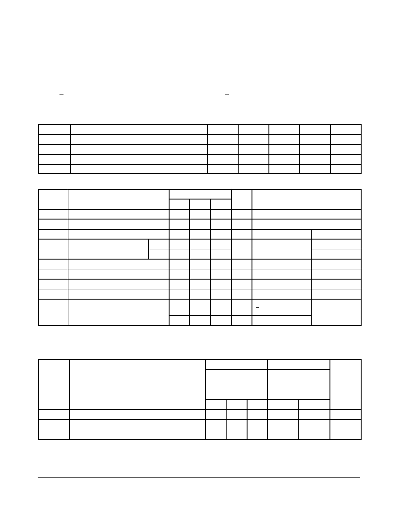
GUARANTEED OPERATING RANGES
Symbol
Parameter
VCC
TA
IOH
IOL
Supply Voltage
Operating Ambient Temperature Range
Output Current — HIGH
Output Current — LOW
Min
Typ
Max
Unit
74
4.5
5.0
5.5
V
74
0
25
70
°C
74
–1.0
mA
74
20
mA
DC CHARACTERISTICS OVER OPERATING TEMPERATURE RANGE (unless otherwise specified)
Limits
Symbol
Parameter
Min Typ Max Unit
Test Conditions
VIH
VIL
VIK
VOH
VOL
IIH
IIL
IOS
ICC
Input HIGH Voltage
2.0
V
Guaranteed Input HIGH Voltage
Input LOW Voltage
0.8
V
Guaranteed Input LOW Voltage
Input Clamp Diode Voltage
Output HIGH Voltage
2.5
2.5
2.7
2.7
–1.2
V
IIN = –18 mA
V
IOH = –1.0 mA
Output LOW Voltage
Input HIGH Current
Input LOW Current
Output Short Circuit Current (Note 2)
Total Supply Current
0.35 0.5
V
IOL = 20 mA
20
µA VIN = 2.7 V
–20
µA VIN = 0.5 V
–60
–150 mA VOUT = 0 V
ICCH 55
72
mA Dn = 4.5 V, CP = ↑,
E = GND
VCC = MIN
VCC = 4.5 V
VCC = 4.75 V
VCC = MIN
VCC = MAX
VCC = MAX
VCC = MAX
VCC = MAX
ICCL 70
90
mA Dn = E = GND, CP = ↑
NOTES:
1. For conditions shown as MIN or MAX, use the appropriate value specified under recommended operating conditions for the applicable device type.
2. Not more than one output should be shorted at a time, nor for more than 1 second.
AC ELECTRICAL CHARACTERISTICS
Symbol
fMAX
tPLH
tPHL
Parameter
Maximum Clock Frequency
Propagation Delay
CP to Qn
74F
TA = +25°C
VCC = +5.0 V
CL = 50 pF
Min Typ Max
110 120
4.0
6.5
8.5
4.0
7.0
9.0
74F
TA = 0 to +70°C
VCC = 5.0 V ± 10%
CL = 50 pF
Min
Max
100
4.0
10
4.0
10.5
Unit
MHz
ns
FAST AND LS TTL DATA
4-279
Share Link: 