TDA4852 데이터 시트보기 (PDF) - Philips Electronics
부품명
상세내역
제조사
TDA4852 Datasheet PDF : 16 Pages
| |||
Philips Semiconductors
Horizontal and vertical deflection controller
for autosync monitors
Preliminary specification
TDA4852
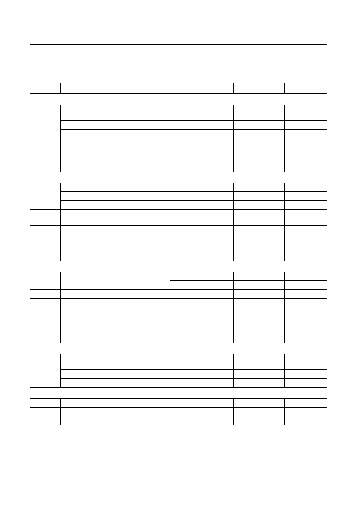
SYMBOL
PARAMETER
CONDITIONS
MIN. TYP. MAX. UNIT
Horizontal oscillator
fosc
centre frequency
ϕH/tH
I18
V18
deviation of centre frequency
temperature coefficient
relative holding/catching range
external oscillator current
voltage at reference current input
(pin18)
Horizontal PLL2
V2
upper clamping level of flyback input
lower clamping level of flyback input
H-flyback slicing level
td/tH
delay between middle of sync and
middle of H-flyback related to tH
V20
upper control voltage limitation
lower control voltage limitation
I20
∆t/tH
control current
PLL2 control range related to tH
Horizontal output (open-collector)
V3
output voltage LOW
tp/tH
tH duty factor
VP
threshold to activate under voltage
protection
∆tH
jitter of horizontal output
E/W output
V11
bottom output signal during mid-scan
(pin 11)
top output signal during flyback
temperature coefficient of output signal
E/W amplitude adjustment (parabola)
V14
input voltage (pin 14)
I14
adjustment current
R18 = 2.4 kΩ (pin 18);
C19 = 10 nF (pin 19)
−
−
0
±6
−0.5
2.35
31.45
−
+200
±6.5
−
2.5
−
kHz
±3
+300
±7.3
−4.3
2.65
%
10−6/K
%
mA
V
Fig.6
I2 = 6 mA
I2 = −1 mA
−
5.5
−
V
−
−0.75
−
V
−
3.0
−
V
−
3.0
−
%
Fig.6
I3 = 20 mA
I3 = 60 mA
horizontal output off
horizontal output on
f = 31 kHz
f = 64 kHz
f = 100 kHz
note 1
internally stabilized
−
6.2
−
V
−
4.8
−
V
−
±0.083I18 −
µA
30
−
−
%
−
−
−
−
42
45
−
5.6
−
5.8
−
−
−
−
−
−
0.3 V
0.8 V
48
%
−
V
−
V
3.5 ns
1.9 ns
1.2 ns
1.05 1.2
1.35 V
4.2
−
Fig.7
100% parabola
typically 28% parabola
−
−110
−
4.5
−
5.0
−120
0
4.8 V
250 10−6/K
−
V
−135 µA
−
µA
Note to the characteristics
1. Parabola amplitude does not track with vertical amplitude adjustment. Tracking can be achieved by a resistor from
vertical amplitude potentiometer to pin 14.
December 1992
9
Share Link: 