AIC1804CCS 데이터 시트보기 (PDF) - Analog Intergrations
부품명
상세내역
제조사
AIC1804CCS Datasheet PDF : 12 Pages
| |||
VCC-VCS < 0.3V is set by the external capacitor
CTI, while the overcurrent delay time 2 and 3
(TOI2 and TOI3) is fixed by IC internal circuit.The
relationship between capacitance of the external
capacitor and delay time is tabulated as below.
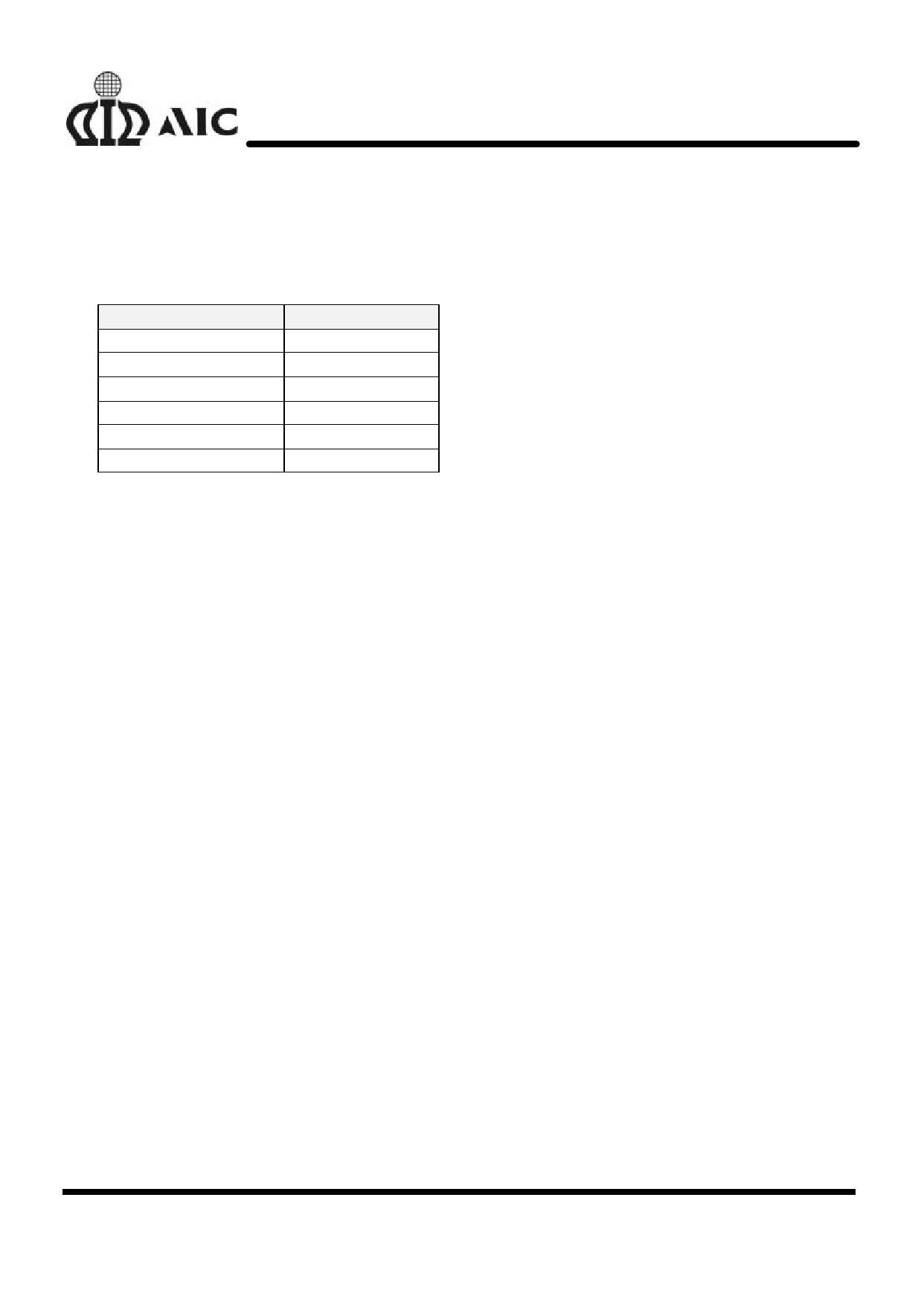
CTI (nF)
1
TOI (mS)
4.8
2.2
15.0
3.3
18.8
5
23.6
6.8
31.0
10
61.8
Selection of External Control
MOSFETs
Because the overcurrent protection voltage is
preset, the threshold current for overcurrent
detection is determined by the turn-on
resistance of the discharge control MOSFET M1.
The turn-on resistance of the external control
MOSFETs can be determined by the equation:
RON=VOIP/IT (IT is the overcurrent threshold
current). For example, if the overcurrent
threshold current TI is designed to be 5A, the
turn-on resistance of the external control
MOSFETs must be 30mΩ. Users should be
aware that turn-on resistance of the MOSFET
changes with temperature variation due to heat
dissipation. It changes with the voltage between
gate and source as well. (Turn-on resistance of
a MOSFET increases as the voltage between
gate and source decreases). Once the turn-on
AIC1804
resistance of the external MOSFET changes,
the overcurrent threshold current will change
accordingly.
Suppressing the Ripple and
Disturbance from Charger
To suppress the ripple and disturbance from
charger, connecting R1 to R4 and C1 to C4 is
recommended. Larger R1 will cause larger error
of battery sense voltage.
Controlling the Charge Control
MOSFET
R5, R6, R7 and NPN transistor Q1 are used to
switch the charge control MOSFET M2. If
overcharge does not occur, no current flows into
OC pin and Q1 is turned off, then M2 is turned
on. When overcharge occurs, current flows into
OC pin and Q1 is turned on, which turns off M2
in turn.
Protection at CS Pin
R8 is used for protection of IC when charger is
connected in reverse. The charge detection
function after overdischarge is possibly disabled
by larger value of R8. Resistance of 1KΩ is
recommended.
10
Share Link: 