EL5421C 데이터 시트보기 (PDF) - Elantec -> Intersil
부품명
상세내역
제조사
EL5421C Datasheet PDF : 13 Pages
| |||
EL5421C
Quad 12MHz Rail-to-Rail Input-Output Buffer
maximum junction temperature for the application to
determine if load conditions need to be modified for the
buffer to remain in the safe operating area.
The maximum power dissipation allowed in a package is
determined according to:
PDMAX = T----J---M-----A----X--Θ---–--J--A-T----A----M-----A----X--
where:
TJMAX = Maximum Junction Temperature
TAMAX= Maximum Ambient Temperature
θJA = Thermal Resistance of the Package
PDMAX = Maximum Power Dissipation in the
Package
The maximum power dissipation actually produced by
an IC is the total quiescent supply current times the total
power supply voltage, plus the power in the IC due to the
loads, or:
PDMAX = Σi[V S × ISMAX + (V S+ – VOUTi ) × ILOADi ]
when sourcing, and:
PDMAX = Σi[VS × ISMAX + (VOUTi – VS- ) × ILOADi ]
when sinking.
Where:
i = 1 to 4 for Quad
VS = Total Supply Voltage
ISMAX = Maximum Supply Current Per Channel
VOUTi = Maximum Output Voltage of the
Application
ILOADi = Load current
If we set the two PDMAX equations equal to each other,
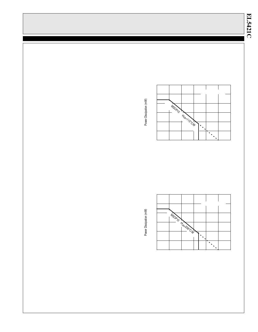
we can solve for RLOADi to avoid device overheat. Fig-
ure 3 and Figure 4 provide a convenient way to see if the
device will overheat. The maximum safe power dissipa-
tion can be found graphically, based on the package type
and the ambient temperature. By using the previous
equation, it is a simple matter to see if PDMAX exceeds
the device’s power derating curves. To ensure proper
operation, it is important to observe the recommended
derating curves shown in Figure 3 and Figure 4.
MSOP10 Package Mounted on JEDEC JESD51-7
High Effective Thermal Conductivity Test Board
1200
1000
870mW
MAX TJ=125°C
800
600
MSOP10---- Θ
400
JA =115°C/W
200
0
0
25
50
75 85 100
125
150
Ambient Temperature (°C)
Figure 3. Package Power Dissipation vs
Ambient Temperature
MSOP10 Package Mounted on JEDEC JESD51-3
Low Effective Thermal Conductivity Test Board
600
500 485mW
400
300
MSOP10---Θ
200
JA =206°C/W
100
MAX TJ=125°C
0
0
25
50
75 85 100
125
150
Ambient Temperature (°C)
Figure 4. Package Power Dissipation vs
Ambient Temperature
Unused Buffers
It is recommended that any unused buffer have the input
tied to the ground plane.
11
Share Link: 