MSM62X42B 데이터 시트보기 (PDF) - Oki Electric Industry
부품명
상세내역
제조사
MSM62X42B Datasheet PDF : 27 Pages
| |||
MSM62X42B
¡ Semiconductor
c) IRQ FLAG (D2) (Interrupt Request FLAG)
This status bit corresponds to "L" or "OPEN" of the STD.P output pin. When STD.P="L", then
this bit=1 and when STD.P=OPEN, then this bit=0.
This bit indicates that an interrupt has occurred to a microcomputer mainly. When D0 of
register CE(MASK)=0, then the STD.P output changes from OPEN to "L" and this bit changes
from "0" to "1" according to the timing set by D3(t1) and D2(t0) of the register CE.
When D1(ITRPT/STND) of the register CE is 1 (interrupt mode), the "1" of this bit (the "L" of
the STD.P output) remains until "0" is written into this bit. When this bit is "1" and timing
for a new interrupt occurs, the new interrupt is ignored. When D1(ITRPT/STND)=0 (fixed
cycle output waveform mode), the "1" of this bit (the "L" of the STD.P output) keeps "1" until
either "0" is written to this bit, or this bit automatically returns after 7.8125ms. The using
examples for the alarm are shown in the item "Set STD.P at alarm mode of APPLICATION
NOTE".
d) 30 sec. ADJ bit (30 sec. ADJUST)
This is a bit for 30-second adjustment. When "1" is written into this bit, the compensation for
30 seconds is performed. The duration for 125µs from the time written into this bit should
not be read from or written into registeres S1 ~ W (addresses 0 ~ C).
This bit for 125µs from the time written into this bit is kept in "1" and then it will automatically
return to "0". After "1" is written into this bit, the registeres S0 ~ W (addresses 0 ~ C) are
operationed with confirmation of automatical return to "0" of this bit.
CE REGISTER (Control E Register)
a) MASK (D0)
This bit controls the STD.P output. When this bit=1, then the STD.P output becomes open.
When this bit=0, then the STD.P output=output mode. The relationship between the MASK
bit and STD.P output is shown as follows.
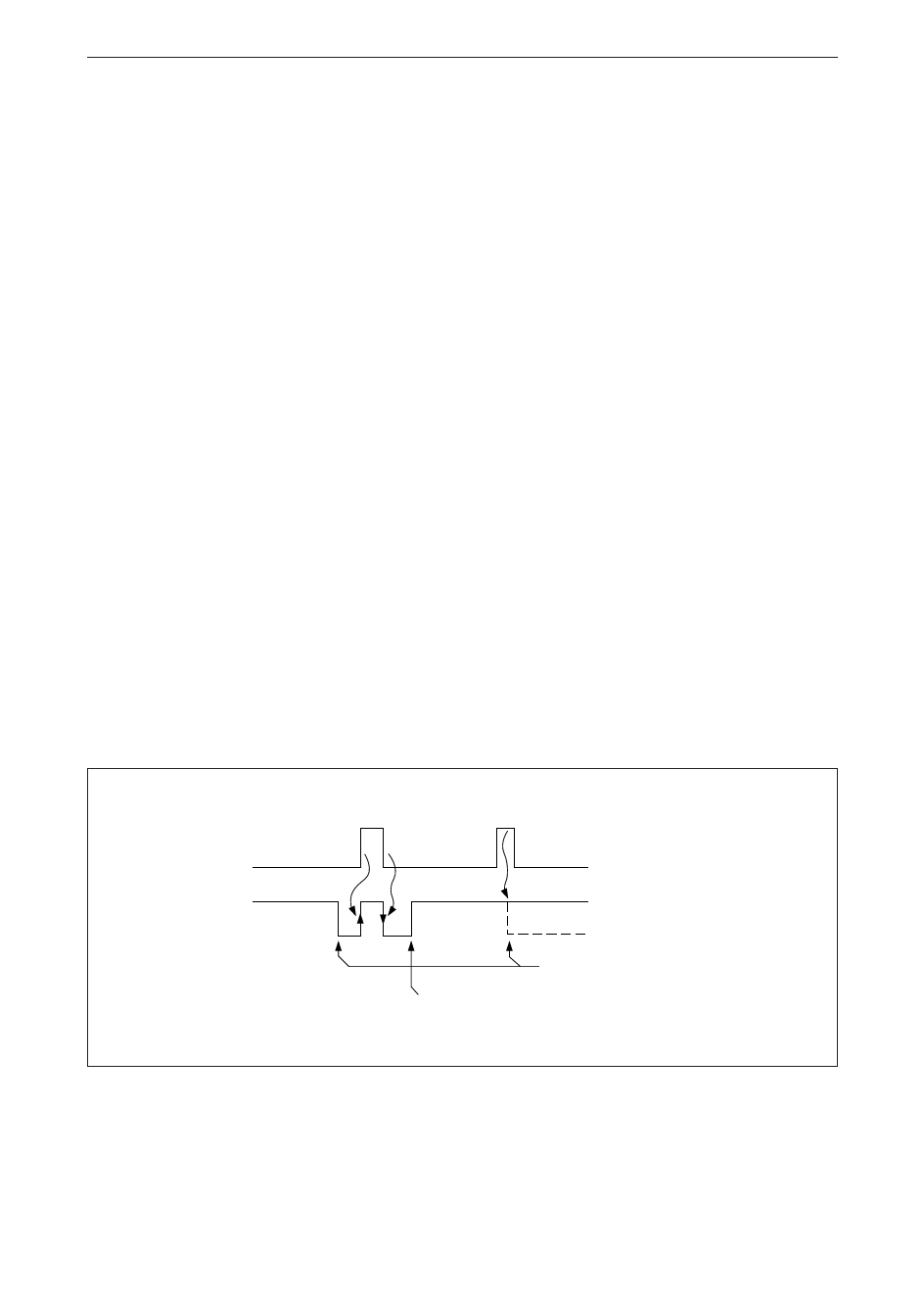
• In the case of interrupt mode (ITRPT/STND bit="1")
• In the case of fixed cycle output waveform mode (ITRPT/STND bit="0")
MASK BIT
"1"
"0"
STD.P OUTPUT
IN TRT/STND BIT = "1"
"1" "INTERRUPT" DOES
NOT OCCUR BECAUSE
"0"
MASK BIT IS "1"
OPEN
LOW LEVEL
"INTERRUPT" TIMING
WRITE “0” INTO IRQ FLAG BIT
54
Share Link: 