EL2257C 데이터 시트보기 (PDF) - Elantec -> Intersil
부품명
상세내역
제조사
EL2257C Datasheet PDF : 21 Pages
| |||
EL2257C/EL2357C
125 MHz Single Supply, Clamping Op Amps
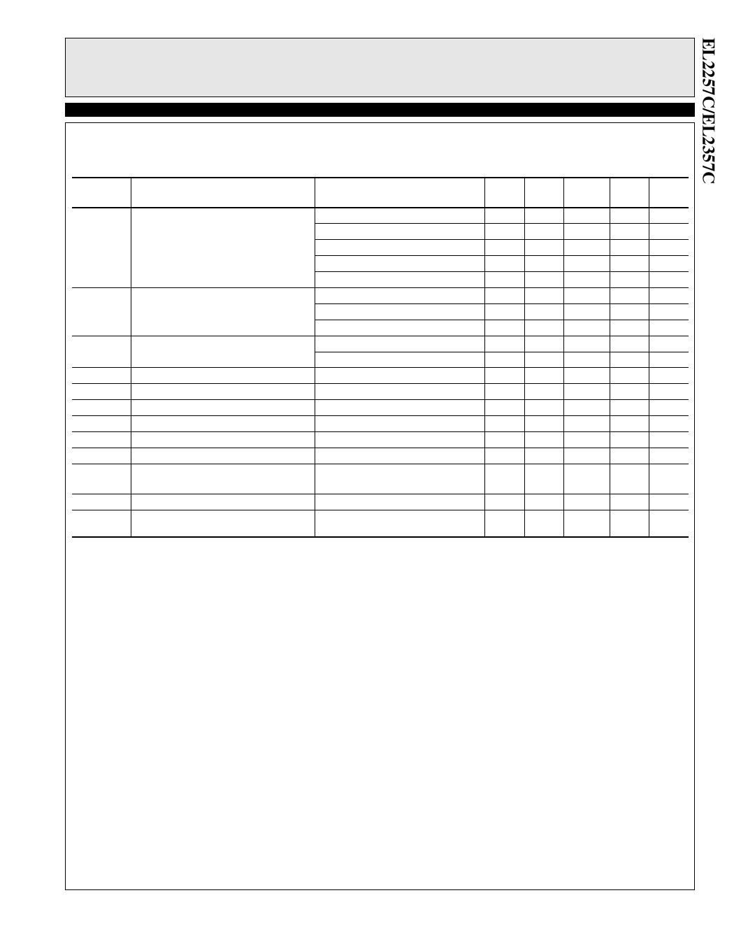
DC Electrical Characteristics (Continued)
VS=+5V, GND=0V, TA=25°C, VCM=1.5V, VOUT=1.5V, VCLAMP=+5V, VENABLE=+5V, unless otherwise specified.
Parameter
Description
VOP
Positive Output Voltage Swing
VON
Negative Output Voltage Swing
IOUT
IOUT,OFF
VIH-EN
VIL-EN
IIH-EN
IIL-EN
VOR-CL
VACC-CL
IIH-CL
IIL-CL
Output Current [1]
Output Current, Disabled
ENABLE pin Voltage for Power Up
ENABLE pin Voltage for Shut Down
ENABLE pin Input Current-High [2]
ENABLE pin Input Current-Low [2]
Voltage Clamp Operating Range [3]
CLAMP Accuracy [4]
CLAMP pin Input Current - High
CLAMP pin Input Current - Low / Per
Amplifier
Test Conditions
VS=+12V, AV=+1, RL=1 kΩ to 0V
VS=+12V, AV=+1, RL=150Ω to 0V
VS=±5V, AV=+1, RL=1 kΩ to 0V
VS=±5V, AV=+1, RL=150Ω to 0V
VS=+3V, AV=+1, RL=150Ω to 0V
VS=+12V, AV=+1, RL=150Ω to 0V
VS=±5V, AV=+1, RL=1 kΩ to 0V
VS=±5V, AV=+1, RL=150Ω to 0V
VS=±5V, AV=+1, RL=10Ω to 0V
VS=±5V, AV=+1, RL=50Ω to 0V
VENABLE=+0.5V
Relative to GND Pin
Relative to GND Pin
VS=VCLAMP=+12V, VENABLE=+12V
VS=VCLAMP=+12V, VENABLE=+0.5V
Relative to GND Pin
VIN=+4V, RL=1 kΩ to GND
VCLAMP=+1.5V and +3.5V
VS=VCLAMP=+12V
VS=+12V, VCLAMP=+1.2V
Min Typ
10.8
9.6
10.0
4.0
3.4
3.8
1.8
1.95
5.5
-4.0
-3.7
±75 ±100
±60
0
2.0
340
0
1.2
-250 100
12
-30
-15
Max
8
-3.4
20
0.5
410
1
VOP
250
25
Test
Level
V
I
V
I
I
I
V
I
I
V
I
I
I
I
I
I
I
Units
V
V
V
V
V
mV
V
V
mA
mA
µA
V
V
µA
µA
V
mV
I
µA
I
µA
1. Internal short circuit protection circuitry has been built into the EL2257C/EL2357C. See the Applications section.
2. If the disable feature is not desired, tie the ENABLE pins to the VS pin, or apply a logic high level to the ENABLE pins.
3. The maximum output voltage that can be clamped is limited to the maximum positive output Voltage, or VOP. Applying a Voltage higher than VOP
inactivates the clamp. If the clamp feature is not desired, either tie the CLAMP pin to the VS pin, or simply let the CLAMP pin float.
4. The clamp accuracy is affected by VIN and RL. See the Typical Curves Section and the Clamp Accuracy vs. VIN and RL curve.
3
Share Link: 