STK6877 데이터 시트보기 (PDF) - SANYO -> Panasonic
부품명
상세내역
제조사
STK6877 Datasheet PDF : 8 Pages
| |||
STK6877
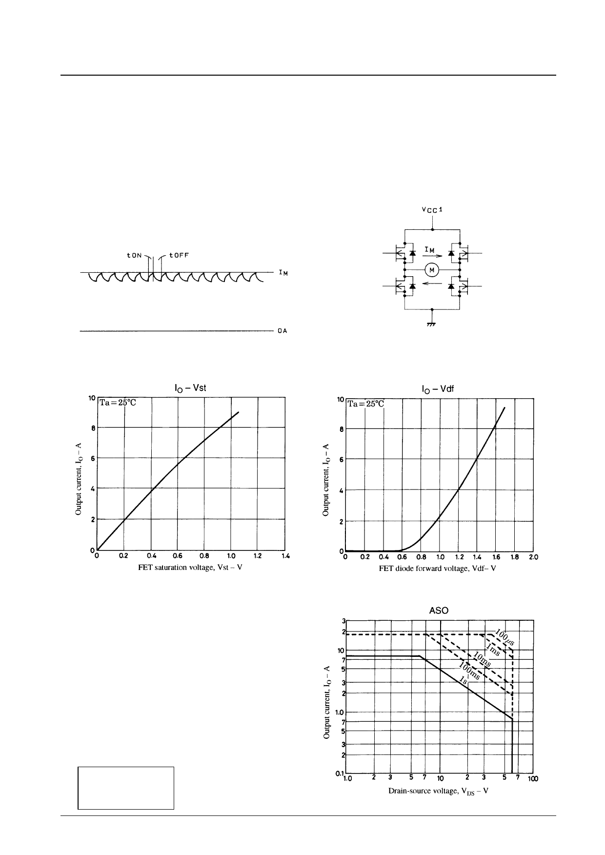
2. Hybrid IC Internal Average Power Dissipation (Pd)
Of the power dissipations within the hybrid IC, the following components have large power dissipations: the FETs that
are the upper PWM elements in the H bridge structure, the lower FETs that form the motor direction reversing loop, and
the flywheel FET body diode. This can be expressed as shown below from experiment (from the output current
waveform in the figure below).
Pd = upper FETs + lower FETs + body diode losses
= Vst × IM × fp × tON + Vst × IM + Vdf × IM × fp × tOFF
Vst: FET saturation voltage (V)
IM: Motor output current (A)
Vdf: FET body diode forward voltage (V)
fp: Chopping frequency (Hz)
Figure 3 IM Waveform Model
Figures 5 and 6 show the IO vs. Vst and IO vs. Vdf characteristics.
Figure 4 Model Circuit Diagram
Figure 5 IO vs. Vst
3. Junction Temperature, Tj
The junction temperatures Tj (°C) for each element (F1, F2,
F3 and F4) can be derived from the formula below from the
power dissipation Pds (W) for each element and the
junction thermal resistances θj-c (°C/W).
Tj = Tc + θj-c × Pds (°C)
Pds: Loss per element
Note that the thermal resistances for the power elements are
as follows.
F1, F2, F3, F4 θj-c = 4 (°C/W)
F1, F2, F3, F4, ASO
Ta = 25°C
1 pulse
Figure 6 IO vs. Vdf
No. 4874-4/8
Share Link: 