CDP68HC68S1 데이터 시트보기 (PDF) - Intersil
부품명
상세내역
제조사
CDP68HC68S1 Datasheet PDF : 14 Pages
| |||
CDP68HC68S1
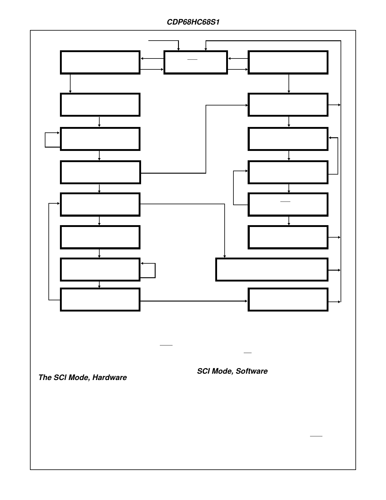
(START)
ANY MESSAGES TO TRANSMIT?
YES = ATTEMPT TO WIN BUS
ARBITRATION
YES
NO
IS IDLE LOW?
TRANSMIT THE MSG ID BYTE.
HAS THE MSG ID BEEN
NO
RECEIVED FROM THE BUS?
YES
DOES THE REC’D MSG ID EQUAL NO = LOST
THE TRANSMITTED MSG ID?
YES = WON BUS ARB.
ARE THERE ANY MORE
NO
MESSAGE BYTES TO TRANSMIT?
YES = SEND REST OF MESSAGE
TRANSMIT THE NEXT MSG
ID BYTE.
NO
ANY MSG ID RECEIVED?
NO
YES = REC. A MSG
NO
IS THIS MESSAGE OF
INTEREST TO US?
YES
SAVE THE RECEIVED BYTE.
YES
HAS THE NEXT BYTE
BEEN RECEIVED YET?
NO
NO
IS IDLE LOW?
YES
PROCESS THE MESSAGE.
HAS THE BYTE BEEN
REC’D FROM THE BUS?
NO
YES
YES DOES THE REC’D BYTE EQUAL NO
THE TRANSMITTED BYTE?
“TRANSMIT” AN END OF MESSAGE CONDITION.
ABORT THIS MESSAGE
TRANSMISSION
DUE TO A COLLISION.
FIGURE 8. GENERAL MESSAGE PROCESSING.
the arbitration-winning MCU) is of any interest. If so, it
should save the incoming message (the length of which may
be specified in the ID byte) and then wait for the IDLE line to
go high before re-attempting transmission (if still desired).
The flowchart in Figure 8 reflects this procedure.
The SCl Mode, Hardware
In the SCl mode, the TxD and RxD pins on the user micro-
computer must be connected to the XMlT and REC pins on
the SBlC chip, respectively, as shown in Figure 9. The
MCU’s SCl port should be configured for the same baud rate
and character format as that used by the bus interface (i.e. 1
start bit, 8 data bits and 1 stop bit). The start and stop bits
are used to synchronize the data, a byte transfers between
the user microcomputer and the SBl chip. When using the
SCl mode, the SBl chip should always be properly mode and
chip selected. This can be accomplished by either a user
microcomputer output signal or by permanent wiring. This is
required in order to always be able to receive messages
from other microcomputers on the bus, which can happen at
random. For the SCl mode, the SBl chip’s MODE pin must
be set to1 and the CS pin to 1.
SCI Mode, Software
The procedure to follow for transmitting/receiving in the SCI
mode is basically identical to that stated in the “Using the
CDP68HC68S1-Software” section above, with the following
exception:
Start of Message Delay
Transmitting a byte via the 68HC05 SCl port basically requires
loading the byte into the MCU’s SCl data register (once the SCI
port is initialized). However, after the SBlC’s IDLE pin drops
low, the user may have to create a delay before transmitting the
FIRST byte of a message; this necessary 2-bit time (256 inter-
nal clock periods) delay is called the Start of Message (SOM)
6-93
Share Link: 