MC3479 데이터 시트보기 (PDF) - Motorola => Freescale
부품명
상세내역
제조사
MC3479 Datasheet PDF : 10 Pages
| |||
MC3479
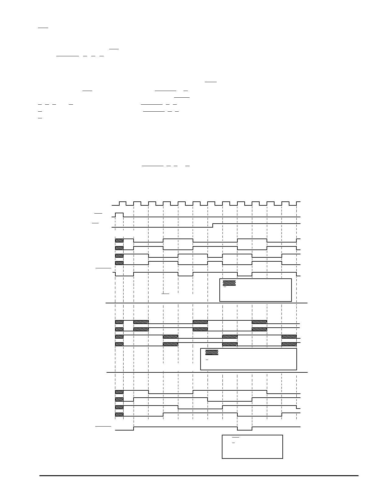
Full/Half Step
When this input is at a Logic “0” (<0.8 V), the outputs
change a full step with each clock cycle, with the sequence
direction depending on the CW/CCW input. There are four
steps (Phase A, B, C, D) for each complete cycle of the
sequencing logic. Current flows through both motor coils
during each step, as shown in Figure 7.
When taken to a Logic “1” (>2.0 V), the outputs change a
half step with each clock cycle, with the sequence direction
depending on the CW/CCW input. Eight steps (Phase A to H)
result for each complete cycle of the sequencing logic. Phase
A, C, E and G correspond (in polarity) to Phase A, B, C, and
D, respectively, of the full step sequence. Phase B, D, F and
H provide current to one motor coil, while de–energizing the
other coil. The condition of the outputs of the de–energized
coil depends on the OIC input, see Figure 7 timing diagram.
outputs to the de–energized coil are in a high impedance
condition — QL and QH of both outputs (Figure 5) are off.
When this input is at a Logic “1” (>2.0 V), a low impedance
output is provided to the de–energized coil as both outputs
have QH on (QL off). To complete the low impedance path
requires connecting VD to VM as described elsewhere in this
data sheet.
Bias/Set
This pin can be used for three functions: a) determining
the maximum output sink current; b) setting the internal logic
to a known state; and c) reducing power consumption.
a) The maximum output sink current is determined by the
base drive current supplied to the lower transistors (QLs of
Figure 5) of each output, which in turn, is a function of IBS.
The appropriate value of IBS is determined by:
OIC
The output impedance control input determines the output
impedance to the de–energized coil when operating in the
half–step mode. When the outputs are in Phase B, D, F or H
(Figure 7) and this input is at a Logic “0” (<0.8 V), the two
IBS = IOD × 0.86
where IBS is in microamps, and IOD is the motor current/coil in
milliamps.
Clk
Bias/Set
CW/CCW
Phase A B
L1
L2
L3
L4
Phase A
Output
Figure 7. Output Sequence
CDA BCB ADCB
(a) Full Step Mode
= High Impedance
F/HS
= Logic “0”
OIC
= Don′t Care
AB C D E F G H A B C D
L1
L2
L3
L4
(b) Half Step Mode
CW/CCW
F/HS
= High Impedance
= Logic “0”
= Logic “1”, OIC = Logic “0”
L1
L2
L3
L4
Phase A
Output
AB C D E F G H A B C D
(c) Half Step Mode
CW/CCW = Logic “0”
F/HS = Logic “1”
OIC
= Logic “1”
6
MOTOROLA ANALOG IC DEVICE DATA
Share Link: 