AT-41411 데이터 시트보기 (PDF) - HP => Agilent Technologies
부품명
상세내역
제조사
AT-41411 Datasheet PDF : 5 Pages
| |||
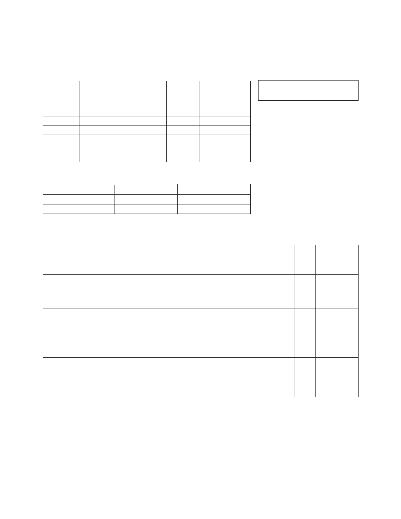
AT-41411 Absolute Maximum Ratings
Symbol
VEBO
VCBO
VCEO
IC
PT
Tj
TSTG
Parameter
Emitter-Base Voltage
Collector-Base Voltage
Collector-Emitter Voltage
Collector Current
Power Dissipation [2,3]
Junction Temperature
Storage Temperature
Units
V
V
V
mA
mW
°C
°C
Absolute
Maximum[1]
1.5
20
12
50
225
150
-65 to 150
Thermal Resistance[2,4]:
θjc = 550°C/W
Notes:
1. Permanent damage may occur if
any of these limits are exceeded.
2. TCASE = 25°C.
3. Derate at 1.8 mW/°C for TC > 26°C.
4. See MEASUREMENTS section
“Thermal Resistance” for more
information.
Part Number Ordering Information
Part Number
Increment
Comments
AT-41411-TR1
3000
Reel
AT-41411-BLK
100
Bulk
Note: For more information, see “Tape and Reel Packaging for Semiconductor Devices”.
Electrical Specifications, TA = 25°C
Symbol
Parameters and Test Conditions[1]
|S21E|2 Insertion Power Gain; VCE = 8 V, IC = 20 mA
P1 dB
G1 dB
Power Output @ 1 dB Gain Compression
VCE = 8 V, IC = 20 mA
1 dB Compressed Gain; VCE = 8 V, IC = 20 mA
f = 1.0 GHz
f = 2.0 GHz
f = 2.0 GHz
Units
dB
dBm
Min.
14.5
Typ.
16.5
11.0
17.0
Max.
f = 2.0 GHz dB
13.0
NFO Optimum Noise Figure: VCE = 8 V, IC = 10 mA
GA
Gain @ NFO; VCE = 8 V, IC = 10 mA
f = 1.0 GHz dB
f = 2.0 GHz
f = 4.0 GHz
f = 1.0 GHz dB
f = 2.0 GHz
f = 4.0 GHz
fT
Gain Bandwidth Product: VCE = 8 V, IC = 20 mA
hFE
Forward Current Transfer Ratio; VCE = 8 V, IC = 10 mA
ICBO Collector Cutoff Current; VCB = 8 V
IEBO Emitter Cutoff Current; VEB = 1 V
GHz
— 30
µA
µA
Notes:
1. Refer to PACKAGING Section, “Tape-and-Reel Packaging for Semiconductor Devices.”
1.4
1.8
3.5
18.0
13.0
9.0
7.0
150 270
0.2
1.0
4-110
Share Link: 