BH7775K 데이터 시트보기 (PDF) - ROHM Semiconductor
부품명
상세내역
제조사
BH7775K Datasheet PDF : 17 Pages
| |||
Video ICs
BH7775K
•Electrical characteristics
• Unless otherwise noted, the following measurement conditions apply:
UNREG – VCC = + 10V
UNREG – VEE = – 10V
Ta = 25°C
∗ With regard to the control voltages, refer to the mode holding voltage range given in p.141.
Output switch control (W1 bit 4, W1 bit 3 and W1 bit 2)
BS Through control (W1 bit 1)
LINE AMP gain (W3 bit 4 and W3 bit 3)
FM output control (W2 bit 5)
FM OUT switch control (W2 bit 4, W2 bit 3 and W2 bit 2)
NTSC / PAL control (W2 bit 0)
Recording MUTE (W2 bit 1)
SP / EP control (W1 bit 5)
FM detector level control (W4 bit 7, W4 bit 6)
ENVE characteristic control (W4 bit 5, W4 bit 4)
MUTE CTRL (pin 22)
LINE MUTE (W1 bit 0)
STEREO
: OFF
: Standard ( + 10.6dB)
: FM output on
: FM REC output MIX ration ( – 10.0dB)
: NTSC
: Recording MUTE
: SP
: Standard
: FNORM detector, no ENVE output
: L (MUTE)
: L (MUTE)
MODEM carrier frequency
NTSC L channel 1.30MHz, PAL Lch 1.40MHz
MODEM carrier frequency
NTSC R channel 1.70MHz, PAL Rch1.80MHz
Color signal subcarrier frequency NTSC
3.579545MHz, PAL 4.433619MHz
Signal frequency f = 1kHz
• Input condition 1 TU input VIN = – 20.0dBV, LINE1 / LINE2 input VIN = – 10.0dBV, BS input VIN = – 16.0dB
• Input condition 2 TU input VIN = – 10.6dBV, LINE1 / LINE2 input VIN = – 0.6dBV, BS input VIN = – 6.6dB
• Input condition 3 TU input VIN = – 15.0dBV, LINE1 / LINE2 input VIN = – 5.0dBV, BS input VIN = – 11.0dB
• Input condition 4 TU input VIN = – 5.0dBV, LINE1 / LINE2 input VIN = + 5.0dBV, BS input VIN = – 1.0dB
∗ 1 B.W. = 0.4 to 30kHz ∗ 2 DIN AUDIO
∗ Refer to Fig. 1 for the measurement circuit.
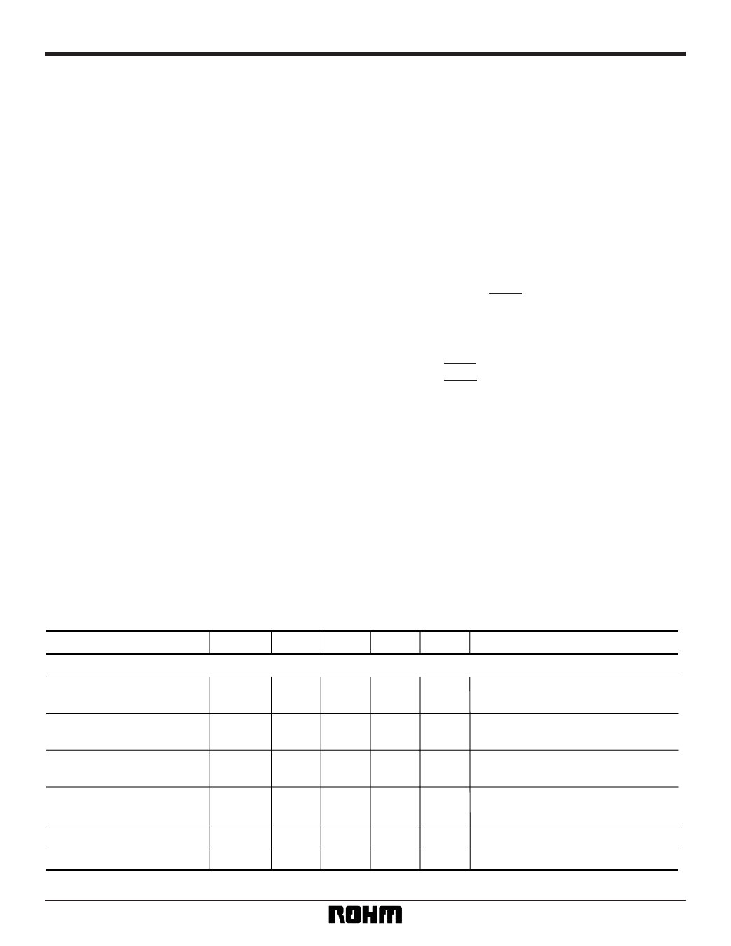
Parameter
[REGULATOR]
Quiescent Current
(positive supply) EE
Quiescent Current
(positive supply) PB
Quiescent Current
(negative supply) EE
Quiescent Current
(negative supply) PB
Regulator input voltage (+)
Regulator input voltage (–)
Symbol Min. Typ. Max. Unit
Iqp EE
29.0 38.6 51.3
mA
Iqp PB
40.3 53.7 71.4
mA
IqM EE – 22.1 – 16.6 – 12.5
mA
IqM PB – 23.9 – 18.0 – 13.5
mA
VCC
4.69 5.04 5.39
V
VEE – 5.37 – 5.02 – 4.67
V
Conditions
EE mode, no input, after carrier
frequency adjustment.
PB mode, no input, FNORM, BPF,
after carrier frequency adjustment.
EE mode, no input, after carrier
frequency adjustment.
PB mode, no input, FNORM, BPF,
after carrier frequency adjustment.
9
Share Link: 