MC100LVEL14 데이터 시트보기 (PDF) - Motorola => Freescale
부품명
상세내역
제조사
MC100LVEL14 Datasheet PDF : 4 Pages
| |||
MC100LVEL14 MC100EL14
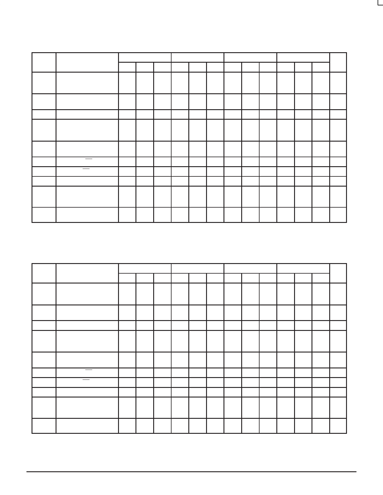
MC100LVEL14 AC/DC CHARACTERISTICS (VEE = –3.8V to –3.0V; VCC = GND)
–40°C
0°C
25°C
85°C
Symbol
Characteristic
Min Typ Max Min Typ Max Min Typ Max Min Typ Max Unit
IEE
Power Supply Current
100LVEL
100EL
32 40
32 40
32 40
32 40
32 40
32 40
mA
34 42
34 42
VBB
Output Ref
Voltage
100LVEL –1.43
100EL –1.38
–1.30 –1.38
–1.26 –1.38
–1.27 –1.35
–1.26 –1.38
–1.25 –1.31
–1.26 –1.38
–1.19 V
–1.26
IIH
tPLH
tPHL
Input High Current
Prop
Delay
CLK to Q (Diff) 520
CLK to Q (SE) 470
SCLK to Q 470
150
720 550
770 500
770 500
150
150
750 580 680 780 630
800 530 680 830 580
800 530 680 830 580
150 µΑ
830 ps
880
880
tSKEW Part-to-Part Skew
Within-Device Skew1
200
200
200
200 ps
50
50
50
50
tS
tH
VPP
VCMR
Setup Time EN
0
Hold Time EN
0
Minimum Input Swing CLK 150
Common Mode Range2
VPP < 500mV –2.0
VPP ≥ 500mV –1.8
0
0
150
–0.4 –2.1
–0.4 –1.9
0
0
150
–0.4 –2.1
–0.4 –1.9
0
0
150
–0.4 –2.1
–0.4 –1.9
ps
ps
mV
V
–0.4
–0.4
tr
Output Rise/Fall Times Q 230
tf
(20% – 80%)
500 230
500 230
500 230
500 ps
1. Skews are specified for identical LOW-to-HIGH or HIGH-to-LOW transitions.
2. The CMR range is referenced to the most positive side of the differential input signal. Normal operation is obtained if the HIGH level falls within
the specified range and the peak-to-peak voltage lies between VPPmin and 1V. The lower end of the CMR range varies 1:1 with VEE. The
numbers in the spec table assume a nominal VEE = –3.3V. Note for PECL operation, the VCMR(min) will be fixed at 3.3V – |VCMR(min)|.
MC100EL14 AC/DC CHARACTERISTICS (VEE = –4.2V to –5.5V; VCC = GND)
–40°C
0°C
25°C
85°C
Symbol
Characteristic
Min Typ Max Min Typ Max Min Typ Max Min Typ Max Unit
IEE
Power Supply Current
100LVEL
100EL
32 40
32 40
32 40
32 40
32 40
32 40
mA
34 42
34 42
VBB
Output Ref
Voltage
100LVEL –1.43
100EL –1.38
–1.30 –1.38
–1.26 –1.38
–1.27 –1.35
–1.26 –1.38
–1.25 –1.31
–1.26 –1.38
–1.19 V
–1.26
IIH
tPLH
tPHL
Input High Current
Prop
Delay
CLK to Q (Diff) 520
CLK to Q (SE) 470
SCLK to Q 470
150
720 550
770 500
770 500
150
150
750 580 680 780 630
800 530 680 830 580
800 530 680 830 580
150 µΑ
830 ps
880
880
tSKEW Part-to-Part Skew
Within-Device Skew1
200
200
200
200 ps
50
50
50
50
tS
tH
VPP
VCMR
Setup Time EN
0
Hold Time EN
0
Minimum Input Swing CLK 150
Common Mode Range2
VPP < 500mV –3.2
VPP ≥ 500mV –3.0
0
0
150
–0.4 –3.3
–0.4 –3.1
0
0
150
–0.4 –3.3
–0.4 –3.1
0
0
150
–0.4 –3.3
–0.4 –3.1
ps
ps
mV
V
–0.4
–0.4
tr
Output Rise/Fall Times Q 230
tf
(20% – 80%)
500 230
500 230
500 230
500 ps
1. Skews are specified for identical LOW-to-HIGH or HIGH-to-LOW transitions.
2. The CMR range is referenced to the most positive side of the differential input signal. Normal operation is obtained if the HIGH level falls within
the specified range and the peak-to-peak voltage lies between VPPmin and 1V. The lower end of the CMR range varies 1:1 with VEE. The
numbers in the spec table assume a nominal VEE = –4.5V. Note for PECL operation, the VCMR(min) will be fixed at 5.0V – |VCMR(min)|.
ECLinPS and ECLinPS Lite
4–3
DL140 — Rev 3
MOTOROLA
Share Link: 