IL1117-5.0 데이터 시트보기 (PDF) - IK Semicon Co., Ltd
부품명
상세내역
제조사
IL1117-5.0 Datasheet PDF : 10 Pages
| |||
IL1117-xx
Application Information
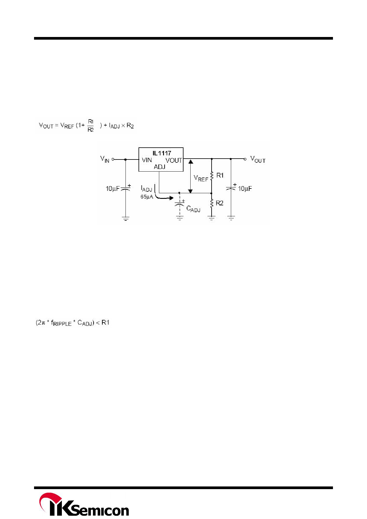
Output voltage adjustment
Like most regulators, the IL1117 regulates the output by comparing the output voltage to an internally gen-
erated reference voltage. On the adjustable version as shown in Fig.4, the VREF is available externally as
1.25V between VOUT and ADJ. The voltage ratio formed by R1 and R2 should be set to conduct 10mA (mi-
numum output load).
The output voltage is given by the following equation:
On fixed versions of IL1117, the voltage divider is provided internally.
Figure 4. Basic Adjustable Regulator
Input Bypass Capacitor
An input capacitor is recommended. A 10μF tantalum on the input is a suitable input bypassing for almost
all applications.
Adjust Terminal Bypass Capacitor
The adjust terminal can be bypassed to ground with a bypass capacitor (CADJ) to improve ripple rejection.
This bypass capacitor prevents ripple from being amplified as the output voltage is increased. At any ripple
frequency, the impedance of the CADJ should be less than R1 to prevent the ripple from being amplified:
The R1 is the resistor between the output and the adjust pin. Its value is normally in the range of 100- 200Ω.
For example, with R1 = 124Ω and fRIPPLE = 120Hz, the CADJ should be > 11μF.
Output Capacitor
IL1117 requires a capacitor from VOUT to GND to provide compensation feedback to the internal gain stage.
This is to ensure stability at the output terminal. Typically, a 10μF tantalum or 50μF aluminum electrolytic is
sufficient.
Note: It is important that the ESR for this capacitor does not exceed 0.5 Ω.
The output capacitor does not have a theoretical upper limit and increasing its value will increase stability.
COUT = 100μF or more is typical for high current regulator design.
Load Regulation
When the adjustable regulator is used (Fig.5), the best load regulation is accomplished when the top of the
resistor divider (R1) is connected directly to the output pin of the IL1117. When so connected, RP is not
multiplied by the divider ratio. For Fixed output version, the top of R1 is internally connected to the output
and ground pins can be connected to low side of the load.
Rev. 02
Share Link: 