TDA8945S 데이터 시트보기 (PDF) - Philips Electronics
부품명
상세내역
제조사
TDA8945S Datasheet PDF : 21 Pages
| |||
Philips Semiconductors
TDA8945S
15 W mono BTL audio amplifier
8.4 Supply Voltage Ripple Rejection (SVRR)
The SVRR is measured with an electrolytic capacitor of 10 µF on pin SVR at a
bandwidth of 10 Hz to 80 kHz. Figure 12 on page 11 illustrates the SVRR as function
of the frequency. A larger capacitor value on the SVR pin improves the ripple rejection
behaviour at the lower frequencies.
8.5 Built-in protection circuits
The TDA8945S contains two types of protection circuits, i.e. short-circuit and thermal
shutdown.
8.5.1 Short-circuit protection
Short-circuit to ground or supply line — This is detected by a so-called ‘missing
current’ detection circuit which measures the current in the positive supply line and
the current in the ground line. A difference between both currents larger than 0.7 A,
switches the power stage to standby mode (high impedance).
Short-circuit across the load — This is detected by an absolute-current
measurement. An absolute-current larger than 3 A, switches the power stage to
standby mode (high impedance).
8.5.2 Thermal shutdown protection
The junction temperature is measured by a temperature sensor; at a junction
temperature of approximately 150 °C this detection circuit switches the power stage
to standby mode (high impedance).
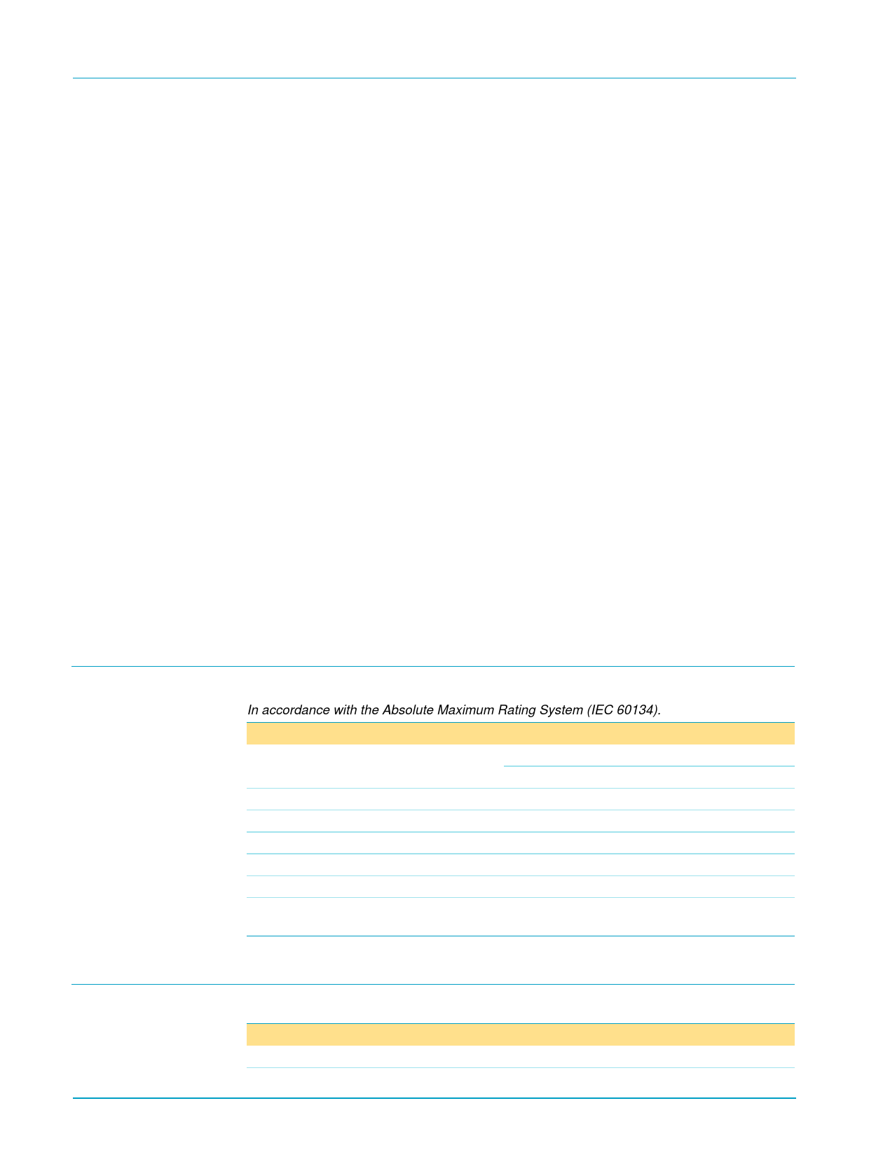
9. Limiting values
Table 5: Limiting values
In accordance with the Absolute Maximum Rating System (IEC 60134).
Symbol Parameter
Conditions
Min
VCC
supply voltage
no signal
−0.3
operating
−0.3
VI
IORM
Tstg
Tcase
Ptot
VCC(sc)
input voltage
repetitive peak output current
storage temperature
non-operating
operating case temperature
total power dissipation
supply voltage to guarantee
short-circuit protection
−0.3
-
−55
−40
-
-
Max
Unit
+25
V
+18
V
VCC + 0.3 V
2
A
+150
°C
+70
°C
14
W
18
V
10. Thermal characteristics
9397 750 06866
Product specification
Table 6: Thermal characteristics
Symbol Parameter
Conditions
Rth(j-mb) thermal resistance from junction to mounting base in free air
Value Unit
9
K/W
Rev. 02 — 7 April 2000
© Philips Electronics N.V. 2000. All rights reserved.
6 of 21
Share Link: 