MAX16809ATU 데이터 시트보기 (PDF) - Maxim Integrated
부품명
상세내역
제조사
MAX16809ATU
Maxim Integrated

MAX16809ATU Datasheet PDF : 23 Pages
| |||
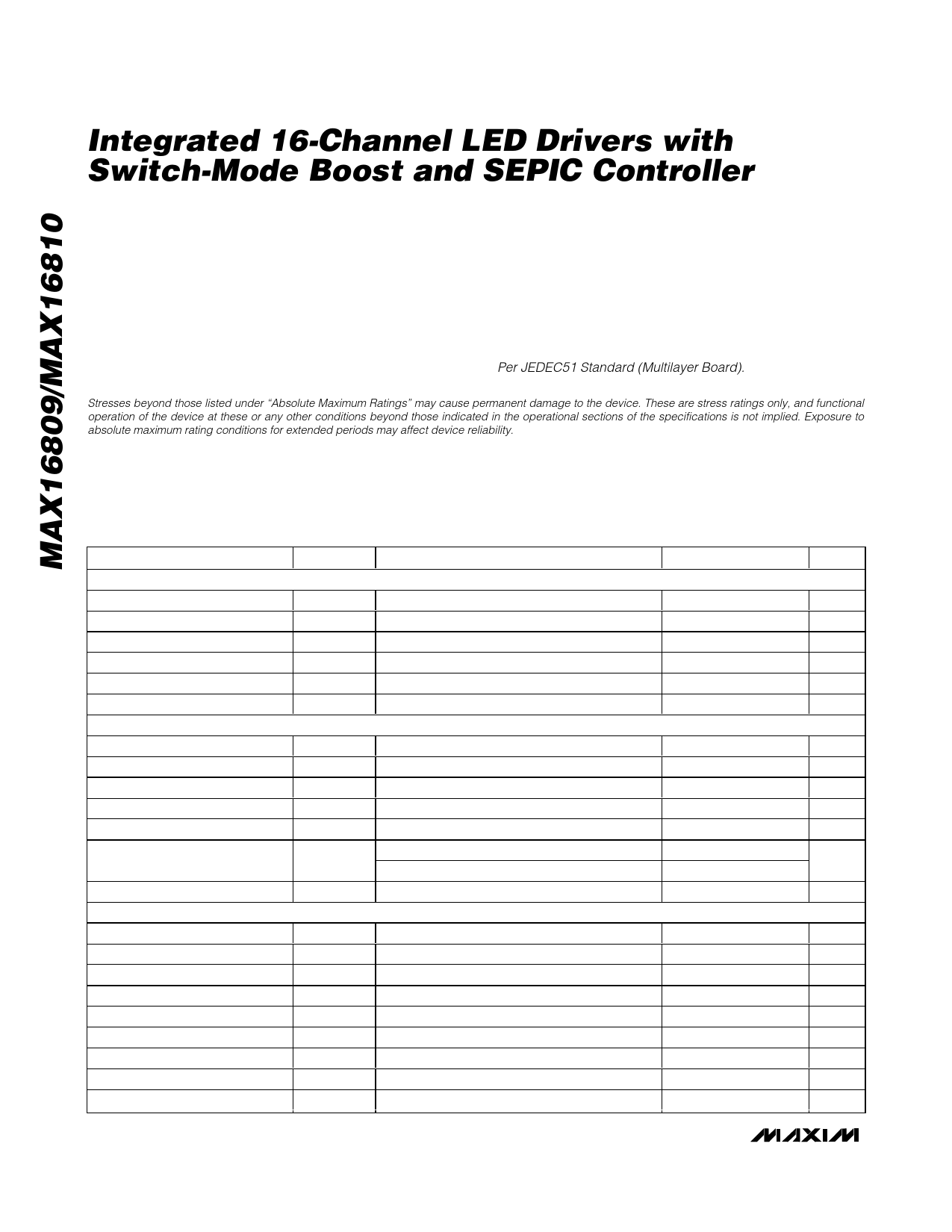
Integrated 16-Channel LED Drivers with
Switch-Mode Boost and SEPIC Controller
ABSOLUTE MAXIMUM RATINGS
VCC to AGND..........................................................-0.3V to +30V
Current into VCC (VCC > 24V) .............................................30mA
V+ to PGND..............................................................-0.3V to +6V
OUT to AGND.............................................-0.3V to (VCC + 0.3V)
OUT Current (10µs duration) .................................................±1A
FB, COMP, CS, RTCT, REF to AGND.......................-0.3V to +6V
COMP Sink Current.............................................................10mA
OUT0–OUT15 to PGND..........................................-0.3V to +40V
DIN, CLK, LE, OE, SET to PGND..................-0.3V to (V+ + 0.3V)
DOUT Current...................................................................±10mA
OUT0–OUT15 Sink Current.................................................60mA
Total PGND Current (1s pulse time) .................................960mA
Continuous Power Dissipation (TA = +70°C)
38-Pin TQFN (derate 35.7mW/°C* above +70°C) ......2857mW
Operating Temperature Range .........................-40°C to +125°C
Junction Temperature ......................................................+150°C
Storage Temperature Range .............................-65°C to +150°C
Lead Temperature (soldering, 10s) .................................+300°C
*Per JEDEC51 Standard (Multilayer Board).
Stresses beyond those listed under “Absolute Maximum Ratings” may cause permanent damage to the device. These are stress ratings only, and functional
operation of the device at these or any other conditions beyond those indicated in the operational sections of the specifications is not implied. Exposure to
absolute maximum rating conditions for extended periods may affect device reliability.
ELECTRICAL CHARACTERISTICS (PWM CONTROLLER)
(VCC = +15V, V+ = +3V to +5.5V referenced to PGND, RT = 10kΩ, CT = 3.3nF, REF = open, COMP = open, CREF = 0.1µF, VFB = 2V,
CS = AGND, AGND = PGND = 0V; all voltages are measured with respect to AGND, unless otherwise noted. TJ = TA = -40°C to
+125°C, unless otherwise noted. Typical values are at TA = +25°C.) (Note 1)
PARAMETER
REFERENCE
Output Voltage
Line Regulation
Load Regulation
Total Output-Voltage Variation
Output Noise Voltage
Output Short-Circuit Current
OSCILLATOR
Initial Accuracy
Voltage Stability
Temperature Stability
RTCT Ramp Peak-to-Peak
RTCT Ramp Valley
Discharge Current
Frequency Range
ERROR AMPLIFIER
FB Input Voltage
Input Bias Current
Open-Loop Gain
Unity-Gain Bandwidth
Power-Supply Rejection Ratio
COMP Sink Current
COMP Source Current
COMP Output-Voltage High
COMP Output-Voltage Low
SYMBOL
CONDITIONS
VREF
∆VLINE
∆VLOAD
VREFT
VNOISE
ISHORT
IREF = 1mA, TJ = +25°C
12V< VCC < 25V, IREF = 1mA
1mA < IREF < 20mA
(Note 2)
10Hz < f < 10kHz
VREF = 0V
TJ = +25°C
12V < VCC < 25V
IDIS
fOSC
VRTCT = 2V, TJ = +25°C
VRTCT = 2V, -40oC ≤ TJ ≤ +125°C
VFB
IB(FB)
AVOL
fGBW
PSRR
ISINK
ISOURCE
VOH
VOL
FB shorted to COMP
2V ≤ VCOMP ≤ 4V
12V ≤ VCC ≤ 25V
VFB = 2.7V, VCOMP = 1.1V
VFB = 2.3V, VCOMP = 5V
VFB = 2.3V, RCOMP = 15kΩ to AGND
VFB = 2.7V, RCOMP = 15kΩ to VREF
MIN TYP MAX UNITS
4.95 5 5.05
V
0.4
4
mV
6
50
mV
4.875
5.125
V
50
µV
30
180
mA
51
54
57
kHz
0.2 0.5
%
1
%
1.7
V
1.1
V
7.9 8.3 8.7
mA
7.5 8.3 9.0
20
1000 kHz
2.45 2.5 2.55
-0.01 -0.1
100
1
60
80
2
6
0.5 1.2 1.8
5
5.8
0.1 1.1
V
µA
dB
MHz
dB
mA
mA
V
V
2 _______________________________________________________________________________________
Share Link: