PE2118 데이터 시트보기 (PDF) - Zetex => Diodes
부품명
상세내역
제조사
PE2118 Datasheet PDF : 9 Pages
| |||
PE2118
The inductor current ripple is typically set for 20% to 40% of the maximum inductor current (IP).
High frequency ferrite core inductor materials reduce frequency dependent power losses
compared to cheaper powdered iron types, improving efficiency. The inductor should have low
ESR (series resistance of the windings) to reduce the I2R power losses, and must be able to
handle the peak inductor current without saturating. Molded chokes and some chip inductors
usually do not have enough core to support the peak inductor currents of 850mA seen on the
PE2118 . To minimize radiated noise, use a toroid, pot core or shielded bobbin inductor. See
Table 1 for some suggested components and suppliers.
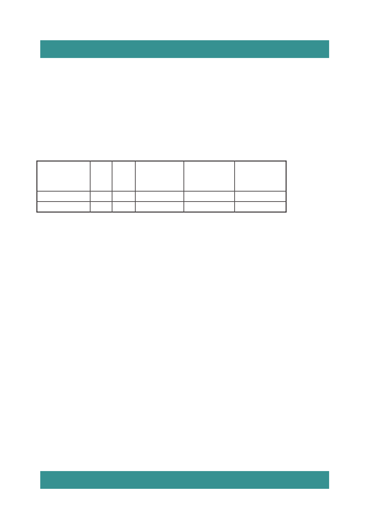
Table 1. Recommended Inductors
PART
CDRH3D16
CDH3B16
L
(µH)
2.2
2.2
MAX
DCR
m
75
70
MAX DC
CURRENT (A)
1.20
1.20
SIZE
W×L×H
(mm3)
3.8 × 3.8 × 1.8
4.0 × 4.0 × 1.8
VENDOR
Sumida
Ceaiya
OUTPUT AND INPUT CAPACITOR SELECTION
Low ESR (equivalent series resistance) capacitors should be used to minimize the output
voltage ripple. Multilayer ceramic capacitors are an excellent choice as they have extremely low
ESR and are available in small footprints. A 4.7µF to 20µF output capacitor is sufficient for most
applications. Larger values up to 22µF may be used to obtain extremely low output voltage
ripple and improve transient response. An additional phase lead capacitor may be required with
output capacitors larger than 10µF to maintain acceptable phase margin. X5R and X7R
dielectric materials are preferred for their ability to maintain capacitance over wide voltage and
temperature ranges.
Low ESR input capacitors reduce input switching noise and reduce the peak current drawn from
the battery. It follows that ceramic capacitors are also a good choice for input decoupling and
should be located as close as possible to the device. A 10µF input capacitor is sufficient for
virtually any application. Larger values may be used without limitations. Table 2 shows a list of
several ceramic capacitor manufacturers. Consult the manufacturers directly for detailed
information on their entire selection of ceramic capacitors.
-8-
Share Link: 