ADJD-J823 데이터 시트보기 (PDF) - Avago Technologies
부품명
상세내역
제조사
ADJD-J823 Datasheet PDF : 18 Pages
| |||
Optical Specifications
Parameter
Symbol
Conditions
Minimum Maximum
Units
Sensor operating detection range
EV
(Note 3 &10) 800
10000
Lux
Serial Interface Timing Information
Parameter
SCL clock frequency
(Repeated) START condition hold time
Data hold time
SCL clock low period
SCL clock high period
Repeated START condition setup time
Data setup time
STOP condition setup time
Bus free time between START and STOP conditions
tHD:STA
tHIGH
tSU:DAT
SDA
Symbol
fscl
tHD:STA
tHD:DAT
tLOW
tHIGH
tSU:STA
tSU:DAT
tSU:STO
tBUF
Minimum Maximum Units
0
100
kHz
4
-
ms
0 (Note 11) 3.45
ms
4.7
-
ms
4.0
-
ms
4.7
-
ms
250
-
ns
4.0
-
ms
4.7
-
ms
tSU:STA
tBUF
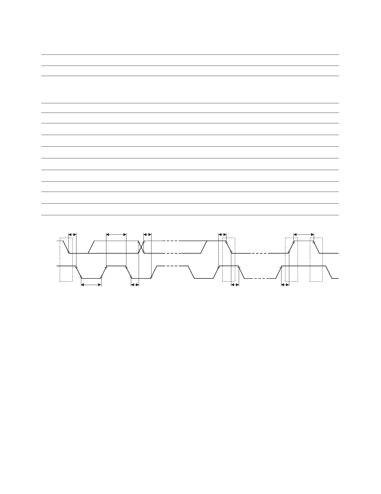
SCL
S
Sr
P
S
tLOW
tHD:DAT
Figure 1. Serial Interface Bus Timing Waveforms
tHD:STA
tSU:STO
Notes:
1. The “Absolute Maximum Ratings” are those values beyond which damage to the device may occur. The device should not be operated at these
limits. The parametric values defined in the “Electrical Specifications” table are not guaranteed at the absolute maximum ratings. The “Recom-
mended Operating Conditions” table will define the conditions for actual device operation.
2. Unless otherwise specified, all voltages are referenced to ground.
3. Specified at room temperature (25°C) and VDDD = VDDA = 2.6V.
4. Applies to all digital input pins.
5. Applies to all digital output pins and CLKIO pin. SDASLV and SDAPROM pins go tri-state when output logic high. Minimum VOH depends on
the pull-up resistor value.
6. Applies to all digital output and digital input-output pins.
7. Dynamic testing is performed with the IC operating in a mode representative of typical operation.
8. Refers to total device current consumption.
9. Output and bidirectional pins are not loaded.
10. Using R:G:B LED light source brightness ratio of 7:13:1 to achieve white D90 color point
Red LED (x,y) = (0.700, 0.300)
Green LED (x,y) = (0.171, 0.715)
Blue LED (x,y) = (0.158, 0.019)
11. A hold time of at least 300ns must be provided internally by a device for the SDA signal ( with reference to the minimum VIH of SCL) to bridge
the undefined region of the falling edge of SCL.
Share Link: 