APU3037 데이터 시트보기 (PDF) - Advanced Power Electronics Corp
부품명
상세내역
제조사
APU3037 Datasheet PDF : 18 Pages
| |||
APU3037 / APU3037A
Note that this method requires that the output capacitor
should have enough ESR to satisfy stability requirements.
In general the output capacitor’s ESR generates a zero
typically at 5KHz to 50KHz which is essential for an
acceptable phase margin.
The ESR zero of the output capacitor expressed as fol-
lows:
FESR
=
2p
3
1
ESR
3
Co
---(8)
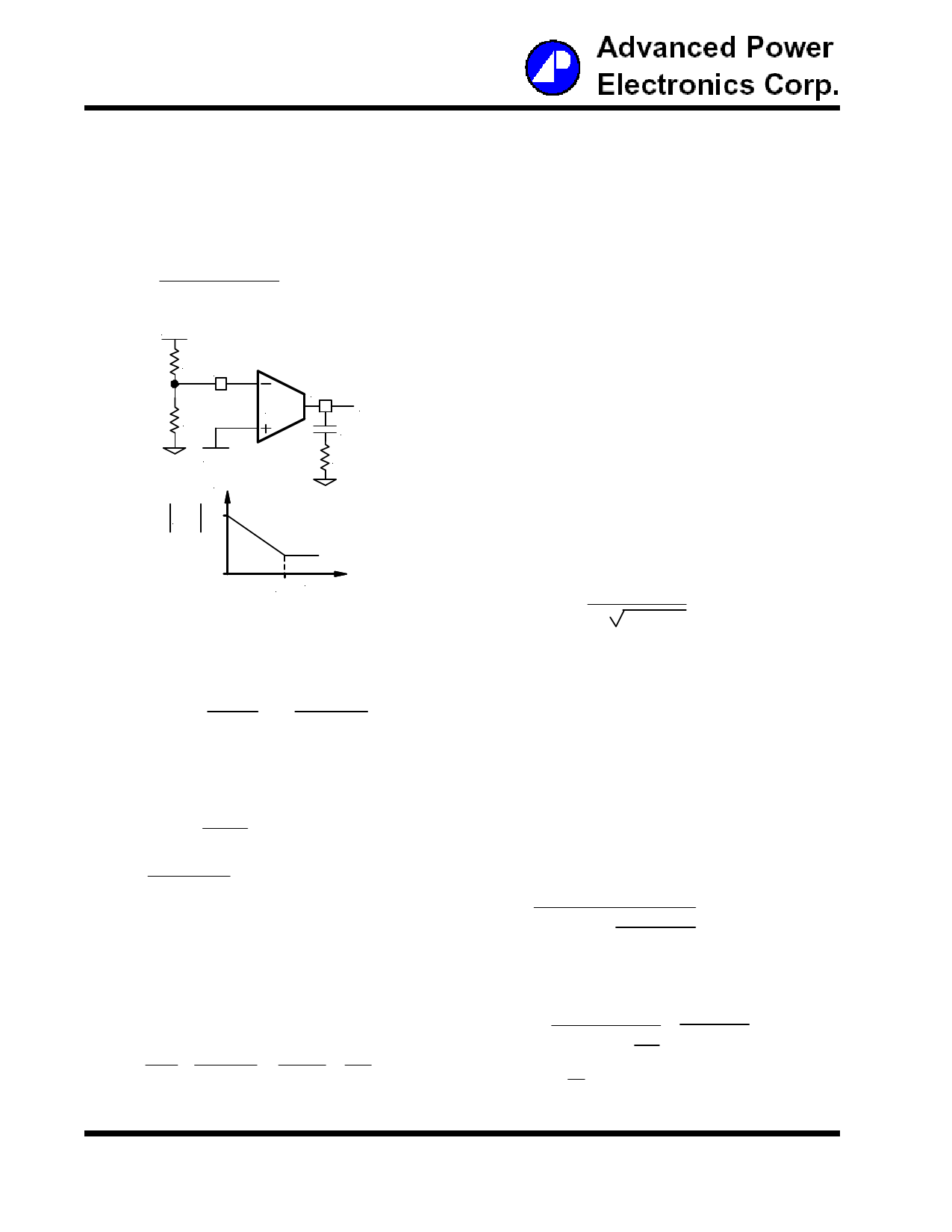
VOUT
R6 Fb
R5
Comp
E/A
Ve
C9
VREF
R4
Gain(dB)
Where:
VIN = Maximum Input Voltage
VOSC = Oscillator Ramp Voltage
Fo = Crossover Frequency
FESR = Zero Frequency of the Output Capacitor
FLC = Resonant Frequency of the Output Filter
R5 and R6 = Resistor Dividers for Output Voltage
Programming
gm = Error Amplifier Transconductance
For:
VIN = 5V
VOSC = 1.25V
Fo = 30KHz
FESR = 26.52KHz
FLC = 2.9KHz
R5 = 1K
R6 = 1.65K
gm = 600mmho
This results to R4=104.4KV. Choose R4=105KV
H(s) dB
To cancel one of the LC filter poles, place the zero be-
fore the LC filter resonant frequency pole:
FZ Frequency
Figure 6 - Compensation network without local
feedback and its asymptotic gain plot.
The transfer function (Ve / VOUT) is given by:
( ) H(s) =
gm
3
R5
R6 + R5
3 1 + sR4C9
sC9
---(9)
The (s) indicates that the transfer function varies as a
function of frequency. This configuration introduces a gain
and zero, expressed by:
|H(s)|
=
gm3
R5
R63R5
3
R4
---(10)
FZ =
1
2p3R43C9
---(11)
The gain is determined by the voltage divider and E/A's
transconductance gain.
FZ ≅ 75%FLC
FZ ≅ 0.75 3
2p
For:
Lo = 10mH
Co = 300mF
FZ = 2.17KHz
R4 = 86.6KV
1
LO 3 CO
---(13)
Using equations (11) and (13) to calculate C9, we get:
C9 = 698pF
Choose C9 = 680pF
One more capacitor is sometimes added in parallel with
C9 and R4. This introduces one more pole which is mainly
used to supress the switching noise. The additional pole
is given by:
1
FP
=
2p
3
R4
3
C9 3 CPOLE
C9 + CPOLE
First select the desired zero-crossover frequency (Fo):
Fo > FESR and FO [ (1/5 ~ 1/10)3 fS
Use the following equation to calculate R4:
R4 =
VOSC
VIN
3
Fo3FESR
FLC2
3
R5 + R6
R5
3
1
gm
---(12)
The pole sets to one half of switching frequency which
results in the capacitor CPOLE:
1
CPOLE =
p3R43fS -
1
≅
1
p3R43fS
C9
fS
for FP << 2
8/18
Share Link: 